Project Overview
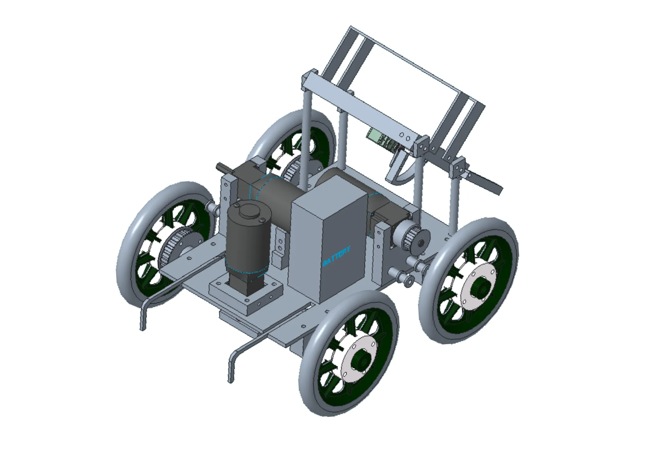
The goal of this project was to design, build, and test a prototype for a search and rescue robot with the objective of delivering a med kit to a target receptacle through an obstacle course.
This project was part of the final assignment for MAE322: Mechanical Design. Each team was allotted a $750 budget and a 3 month timeframe.
Objective
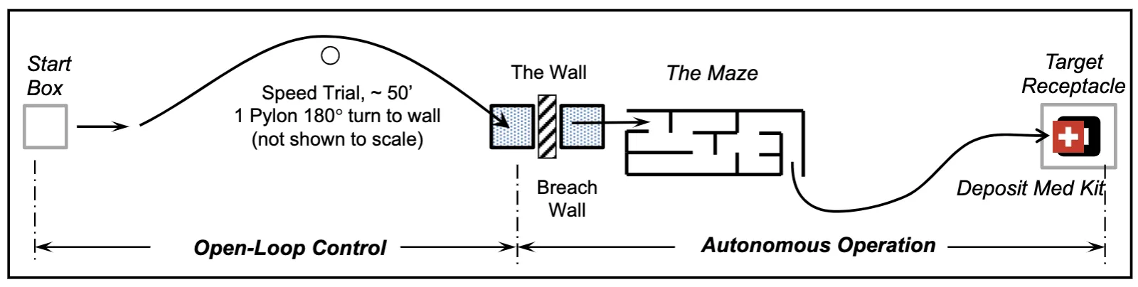
With the goal of delivering a medical kit through an obstacle course and breaching a wall, our team laid out the following requirements needed for a successful robot:
- Fast movement
- Ability to operate closed-loop portions without manual intervention
- Lightweight
- Low-cost and within budget
As team leader, in efforts to optimize our work schedule, I divided our team of 6 members into 3 groups with each group in charge of a subsystem of the robot:
- Group 1: Drive
- Group 2: Lift
- Group 3: Med Kit Dispense
Design Process
Drive Subsystem
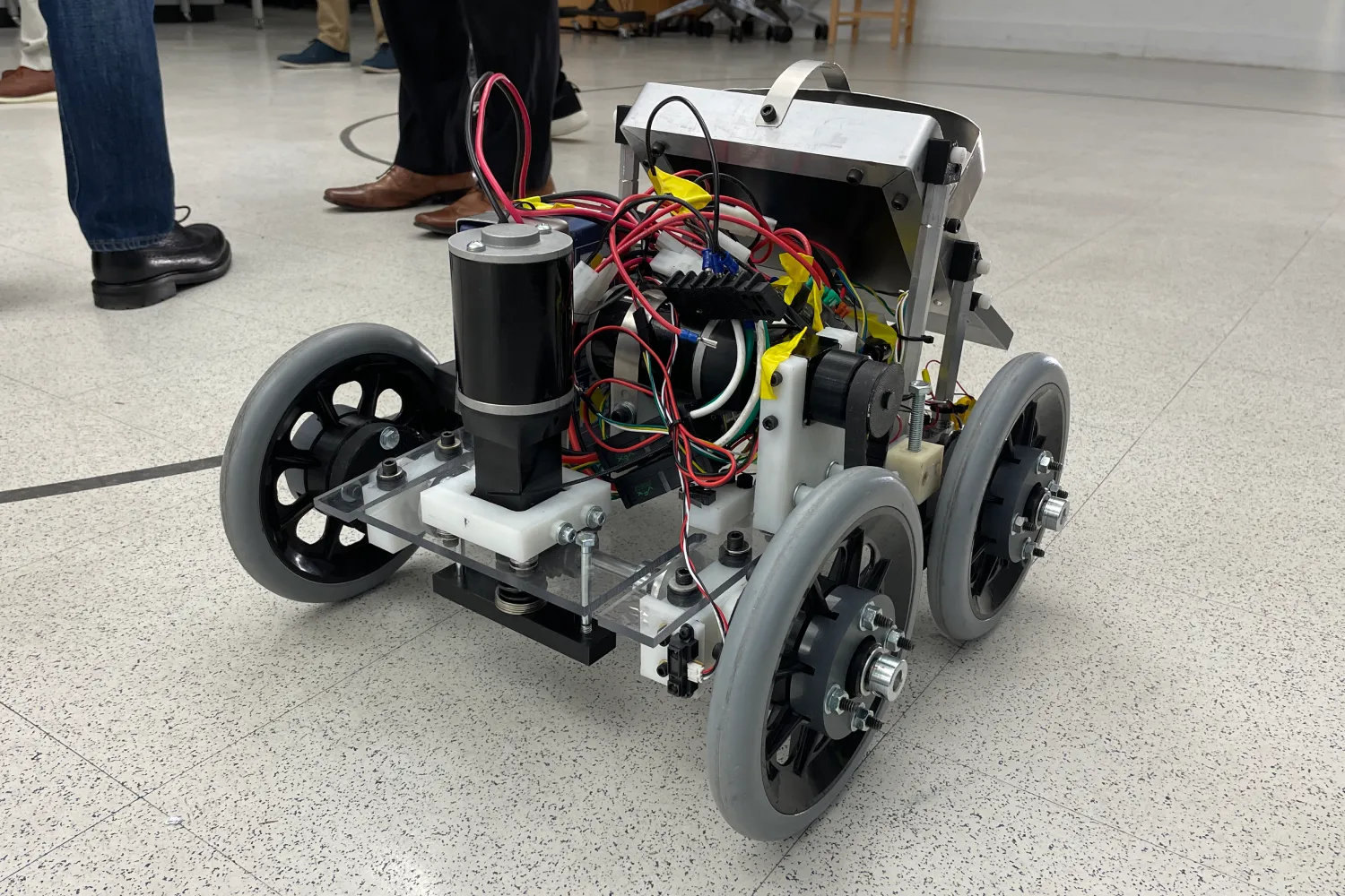
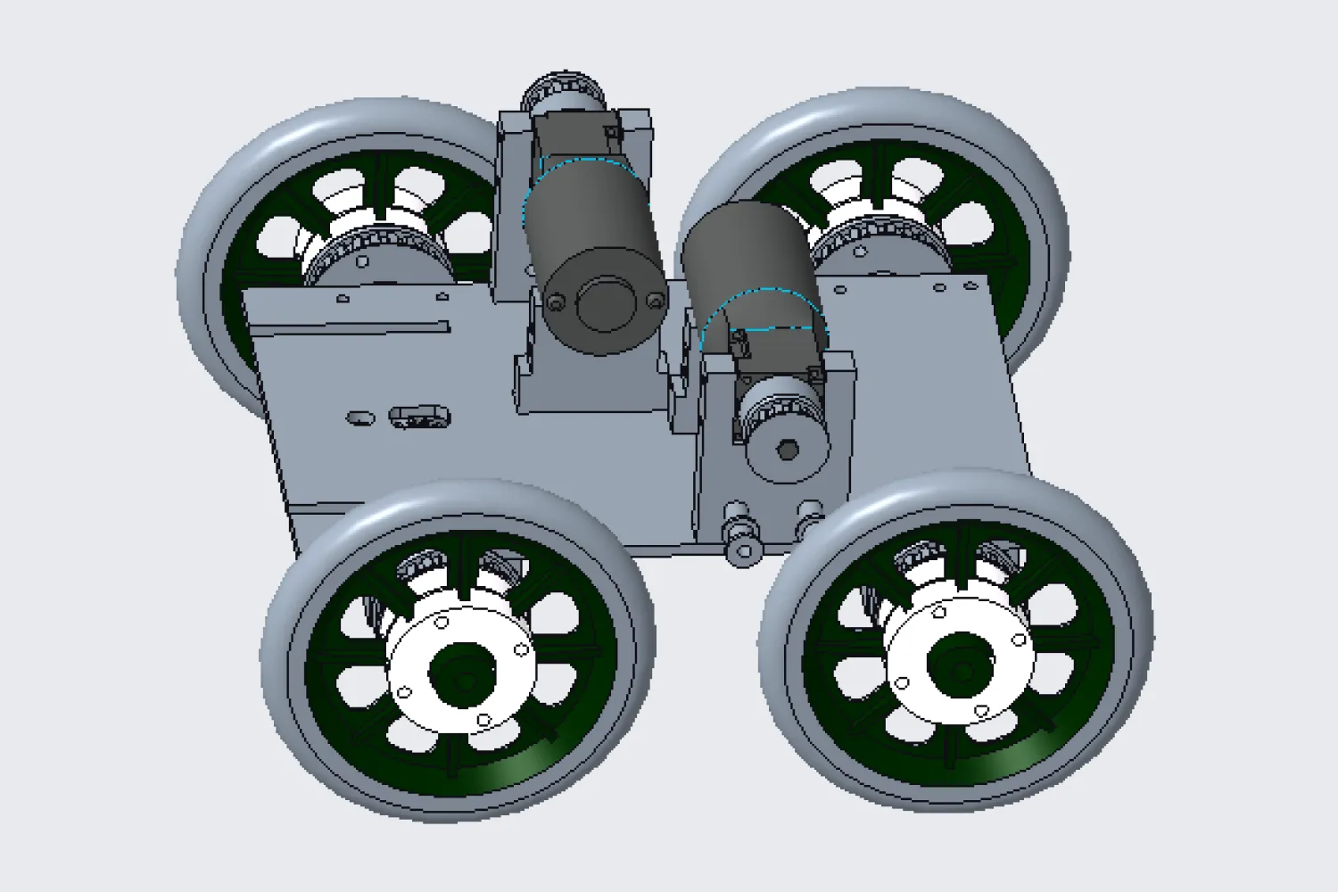
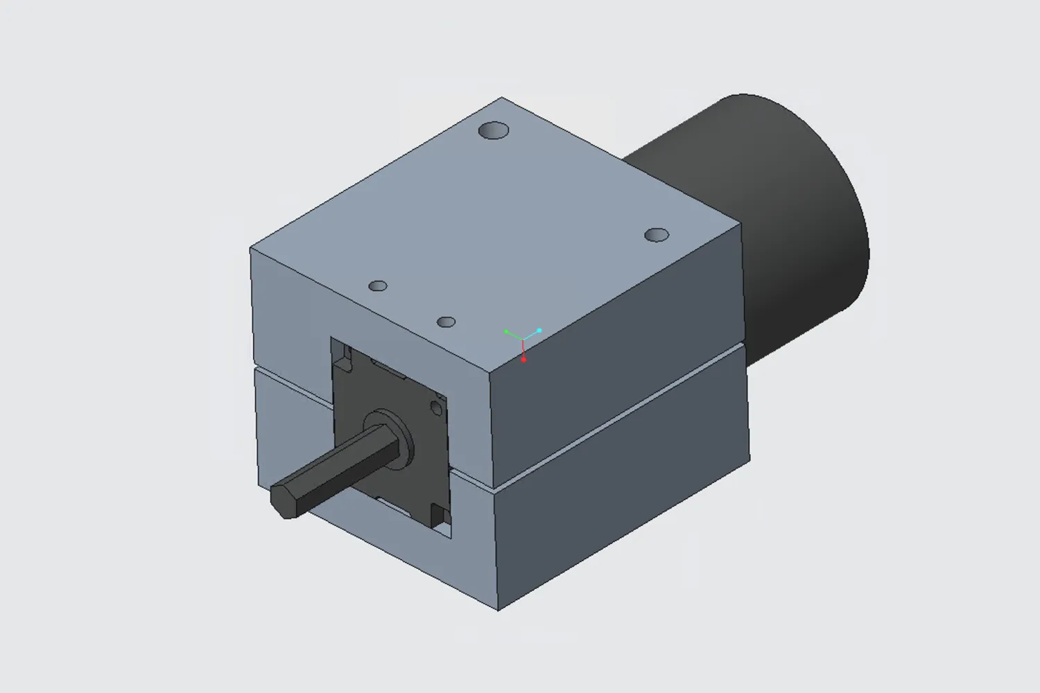
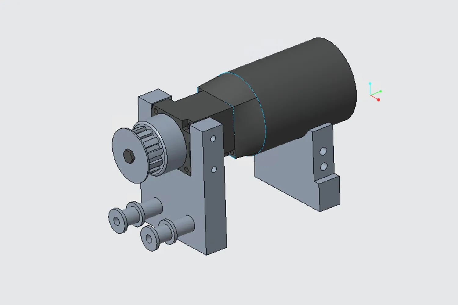
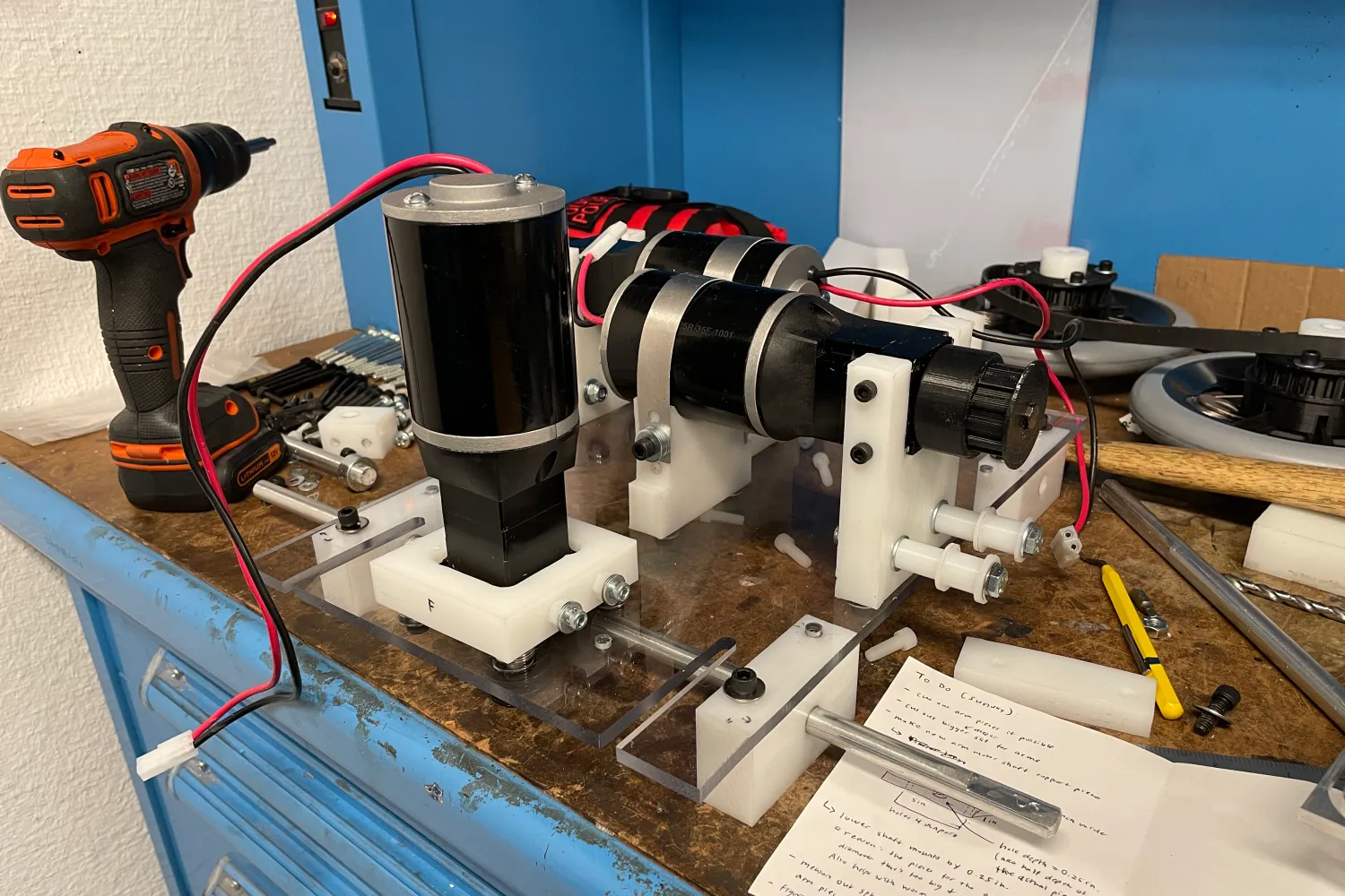
As part of the drive team, one of my responsibilities was figuring out the chassis and motor mounting system. Rather than using the original motor mount pieces that were provided to us in our sample robot, I wanted to redesign them to reduce weight and increase space on the chassis.
In Creo, I took the original motor mount design and split it into two separate components. The front mount was designed to allow for milling while the back mount had to be designed for CNC machining due to the more complex geometry of the arc.
Finally, in an effort to increase chassis strength, I opted to switch our chassis material from its original 1/4” acrylic sheet to a 1/4” polycarbonate sheet.
Lift Subsystem
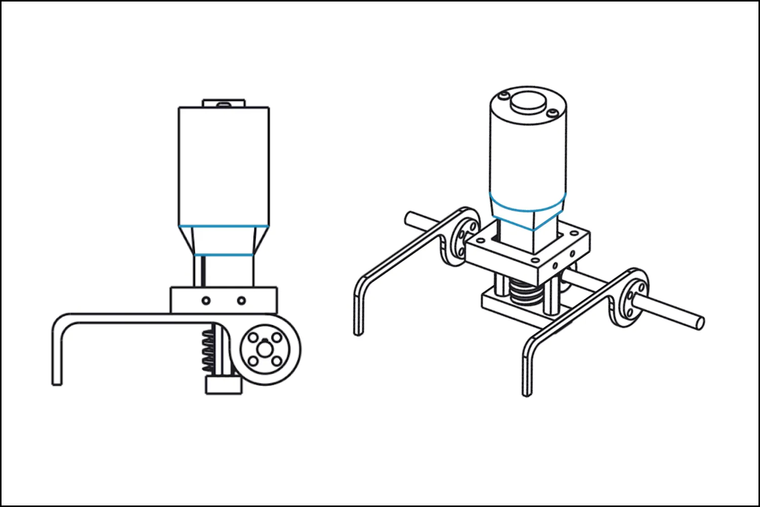
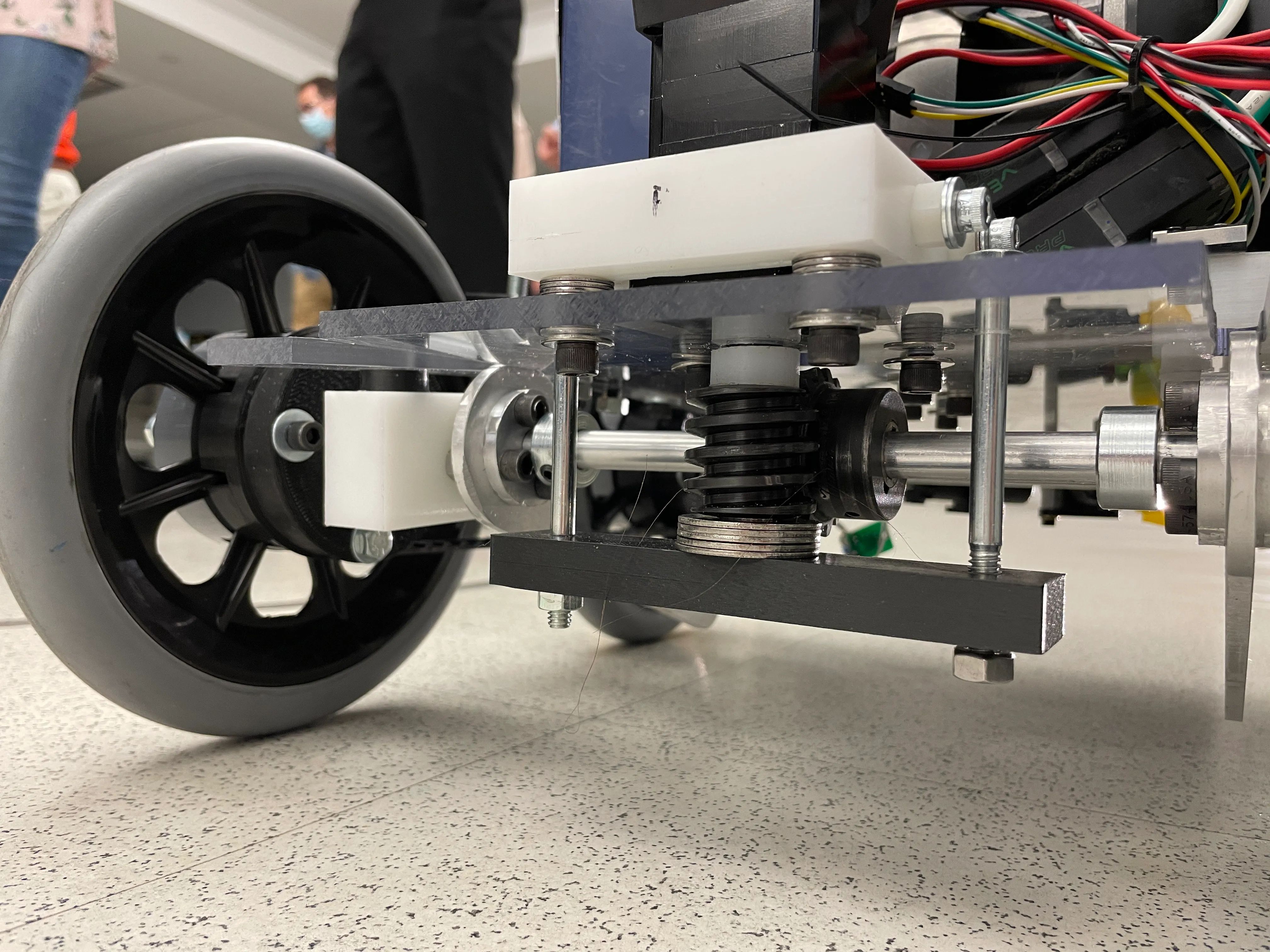
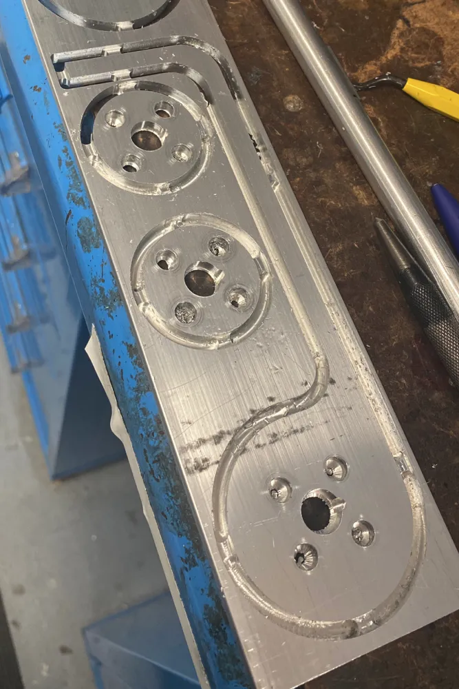
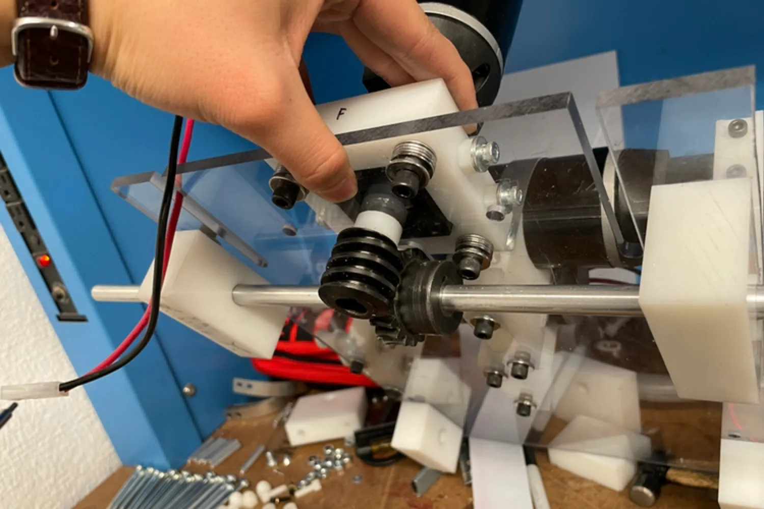
One portion of the obstacle course that we knew would be the most difficult was the breaching of the wall. Therefore, we designed an arm mechanism that would provide leverage to lift the robot’s front wheel off the ground onto the first step.
The arms were CNC machined out of a 1/4” 6061 aluminum plate with a keyway to allow for the arms to rotate with the shaft. The system was powered by a worm gear connected to a drill motor, with a gear reduction to allow the arms to rotate at ~1 RPM.
Final Design & Results
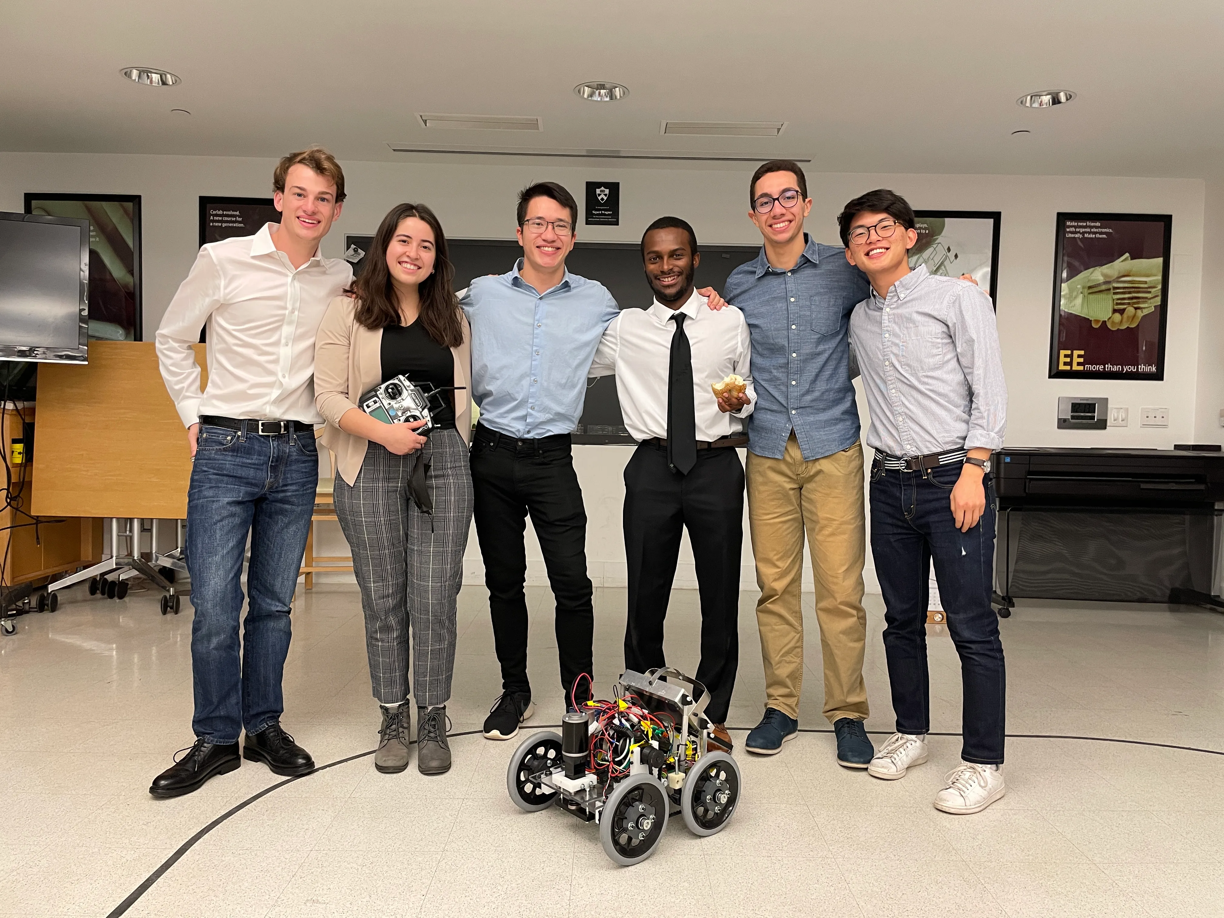
- Reduced overall weight of the motor mounts from 0.79 pounds to 0.37 pounds (53% decrease), also creating additional room for electronics mounting
- Increased chassis impact strength by 4000% by switching from an acrylic base to a polycarbonate base
- Successfully survived the drop test, navigated the driver course, and autonomously found the light source and deposited the med kit
Challenges and Solutions
Design for Manufacturing (DFM)
Challenge
- Given that it was the first time many of us had designed components in CAD, we failed to think ahead about the nuances that come with different kinds of manufacturing processes.
Solution
- Using the mistakes from building these various components, we can incorporate the considerations into our future designs depending on the type of manufacturing.
- CNC/mill
- Create dog bone fillets for sharp corners
- Plan ahead about milling orientations
- 3D Printing
- Increase hole tolerances when working with PLA in order to compensate for shrinking material after cooling
- Design with print orientation in mind to reduce support material and ensure forces act perpendicularly to layer lines
- CNC/mill
Time Management
Challenge
- Given that we were only allowed to use heavy machinery shop equipment when supervisors were present (lathes, mills, CNC), we struggled to have all of our parts fabricated in time for proper testing and debugging prior to demonstration day.
Solution
- In addition to prioritizing our time for manufacturing any parts that required shop equipment, we should have assumed longer production times than initially estimated
- Given that this project was the first time for all of our team members to use these machines, we should have given ourselves a greater buffer period given the learning curve of operating each machine