Project Overview
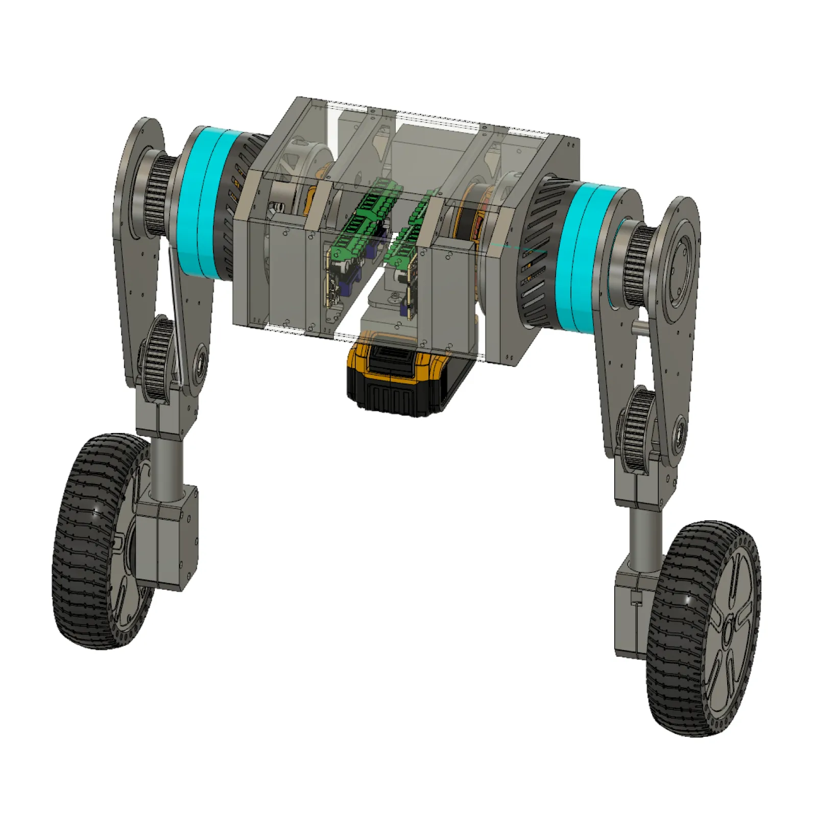
The goal of this project was to create a low-cost, easily manufacturable wheeled bipedal robot platform for use in research applications.
The robot was designed, prototyped, manufactured, and coded by myself in an 8 month timeline.
All components were designed to use either off-the-shelf hardware or be manufactured using easily accessible lab equipment including FDM 3D printers, laser cutters, and basic hand/shop tools.
Objective
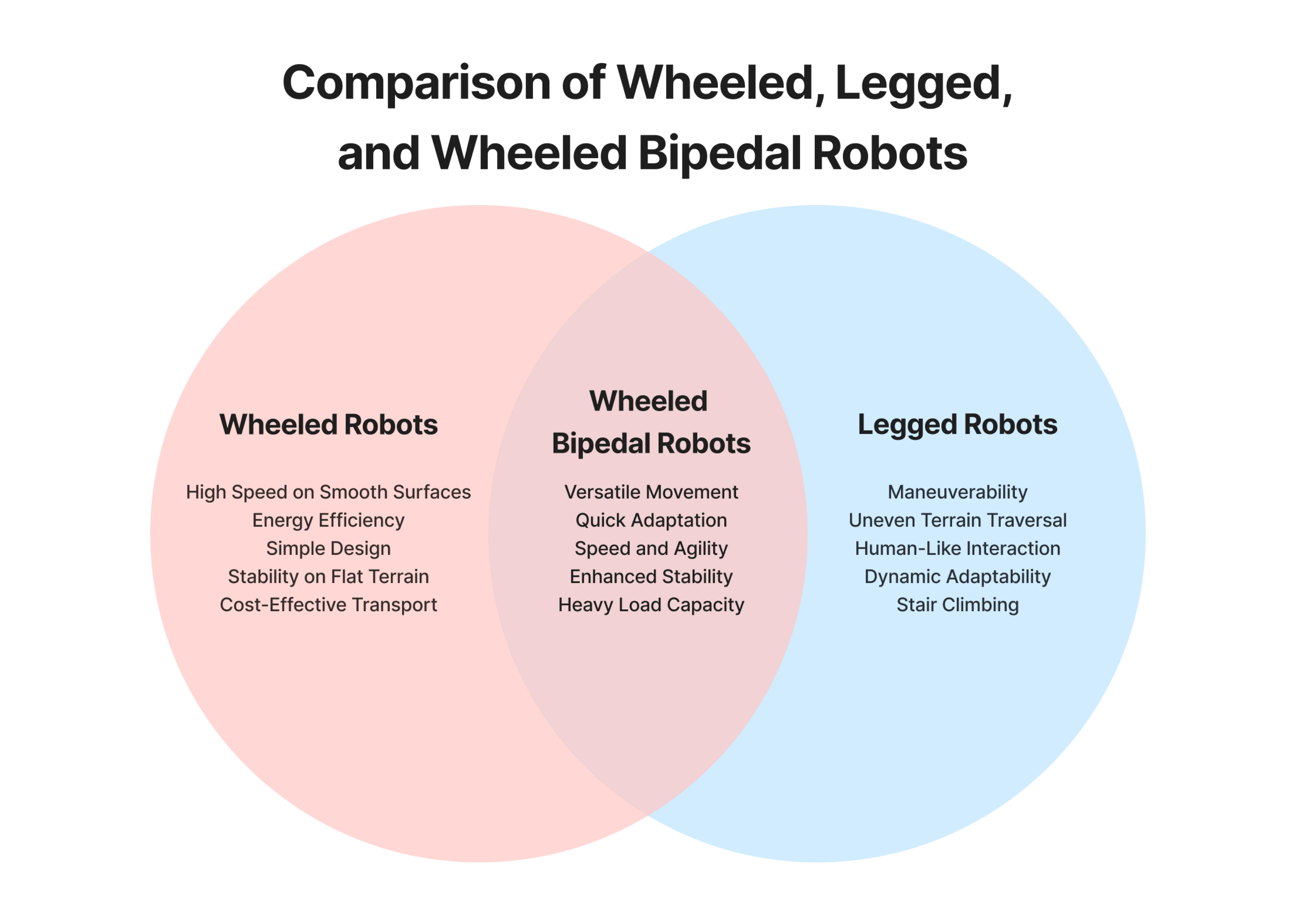
Wheeled bipedal robots combine the strengths of wheeled and legged locomotion, offering fast, efficient movement on smooth surfaces and adaptability on rough terrain. Despite their potential, this field remains understudied.
This project presents a cost-effective, easily manufacturable design for a wheeled bipedal robot, intended as a flexible starting point for research groups. The design prioritizes affordability and accessibility, requiring minimal equipment for construction.
By offering a foundational hardware and electronics framework, this project aims to advance research in wheeled bipedal robots and foster further development in this emerging field.
Design Process
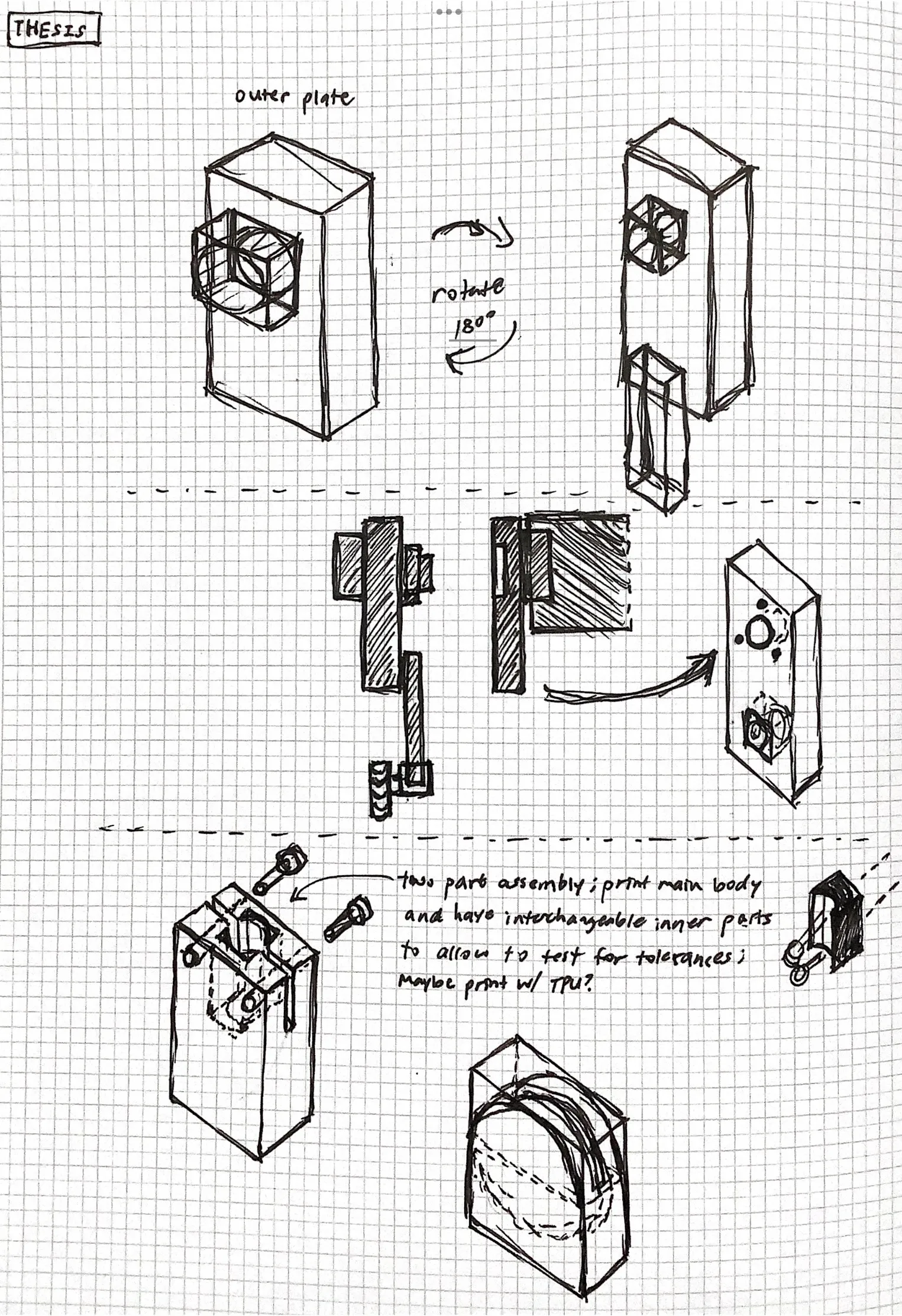
Concept sketches
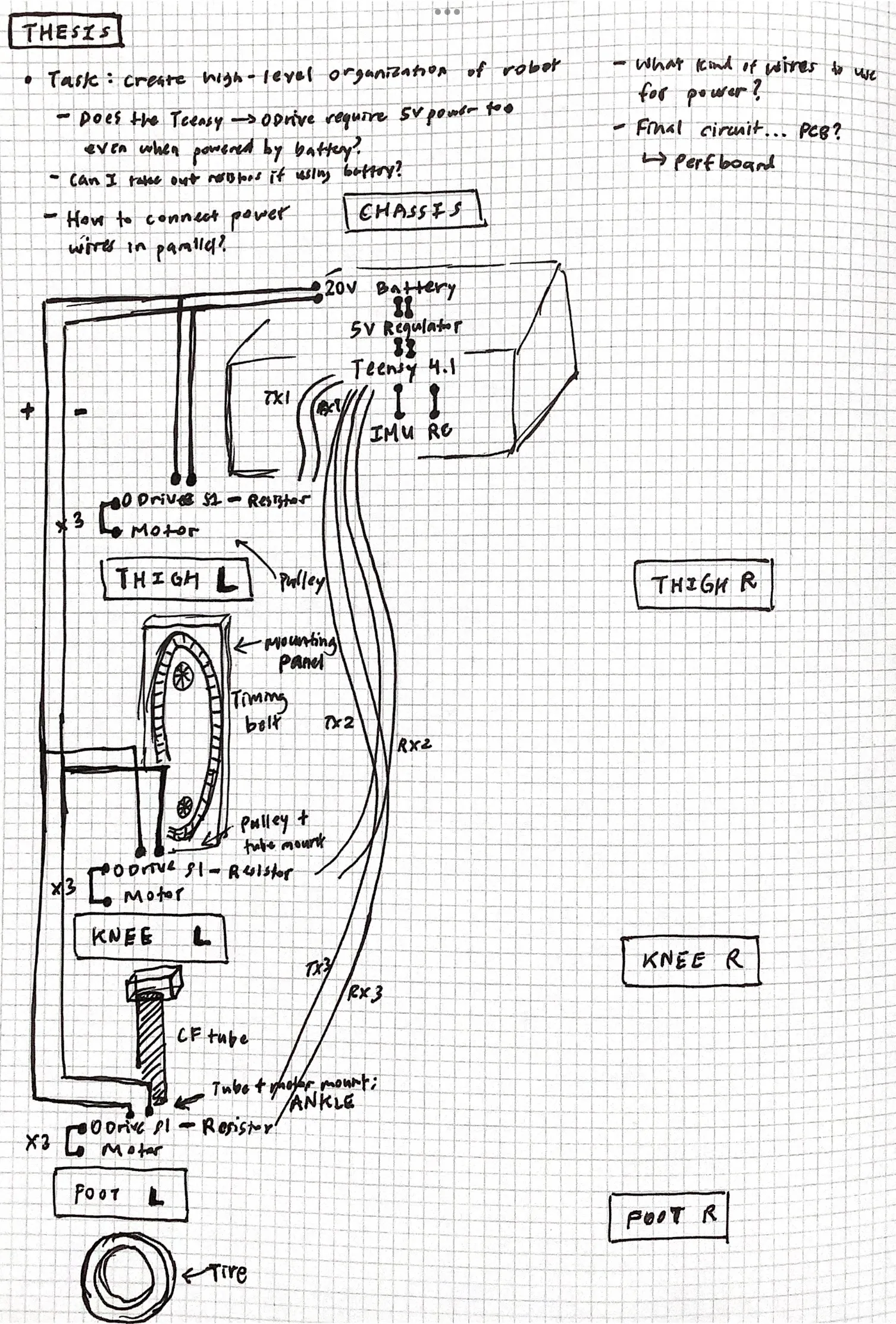
Early CAD
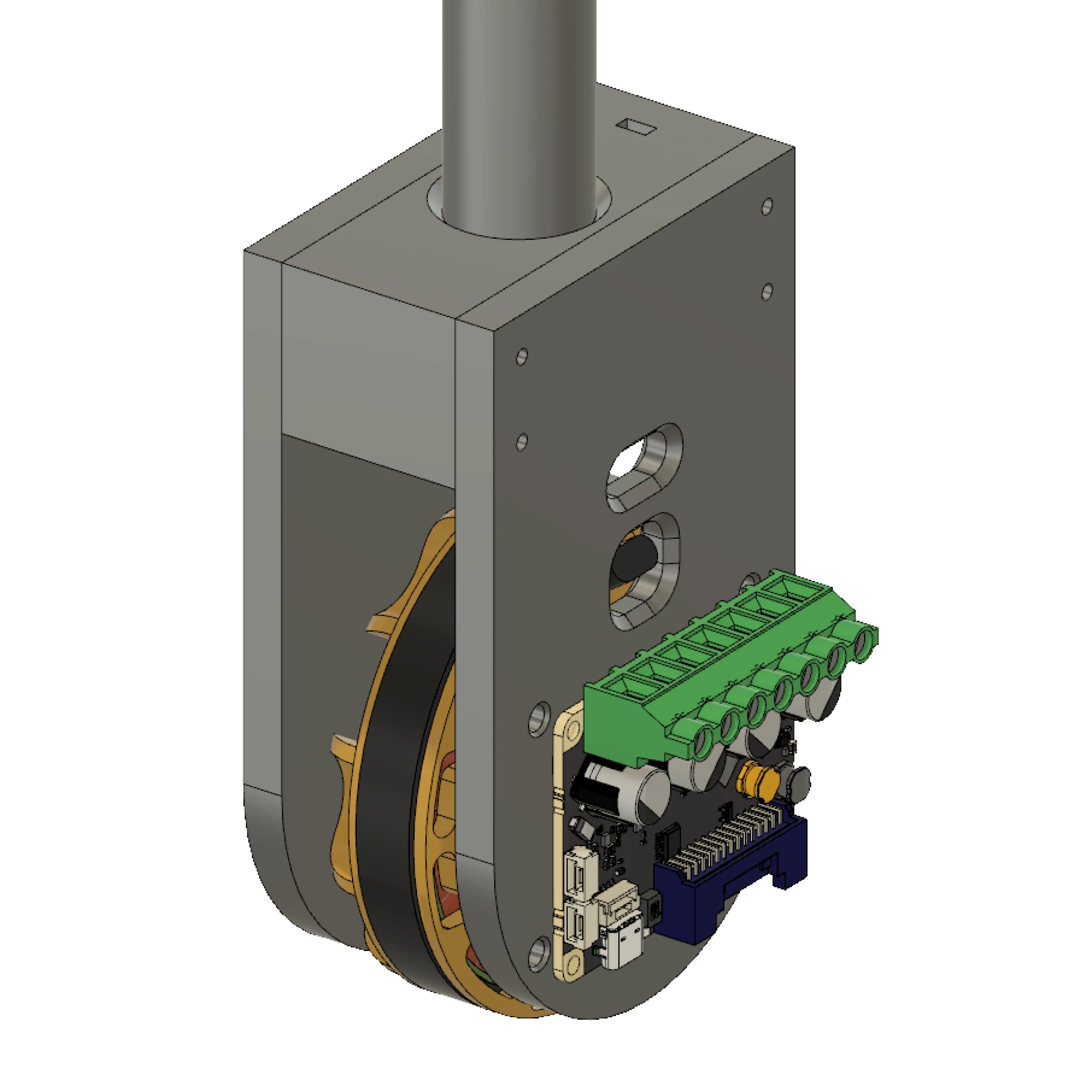
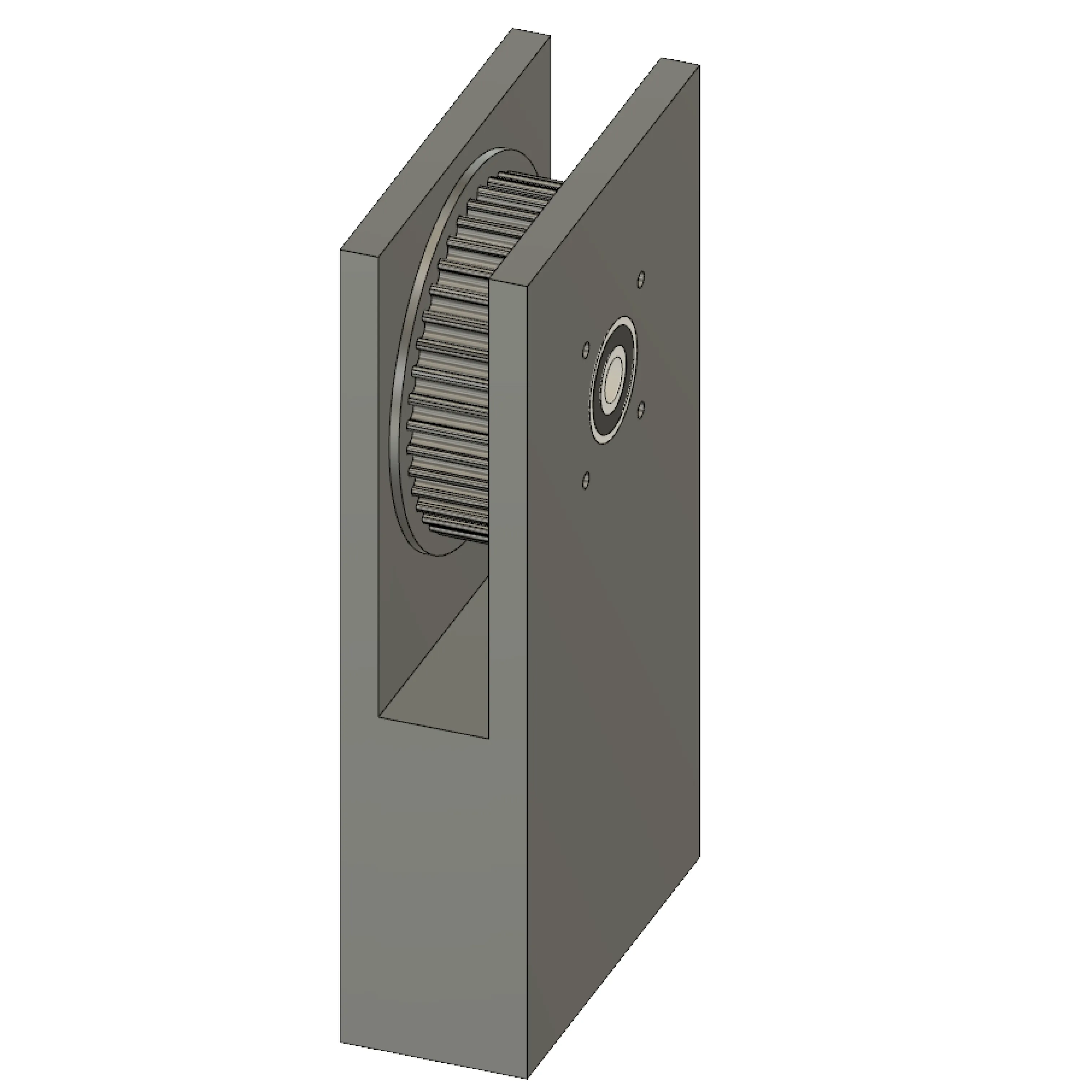
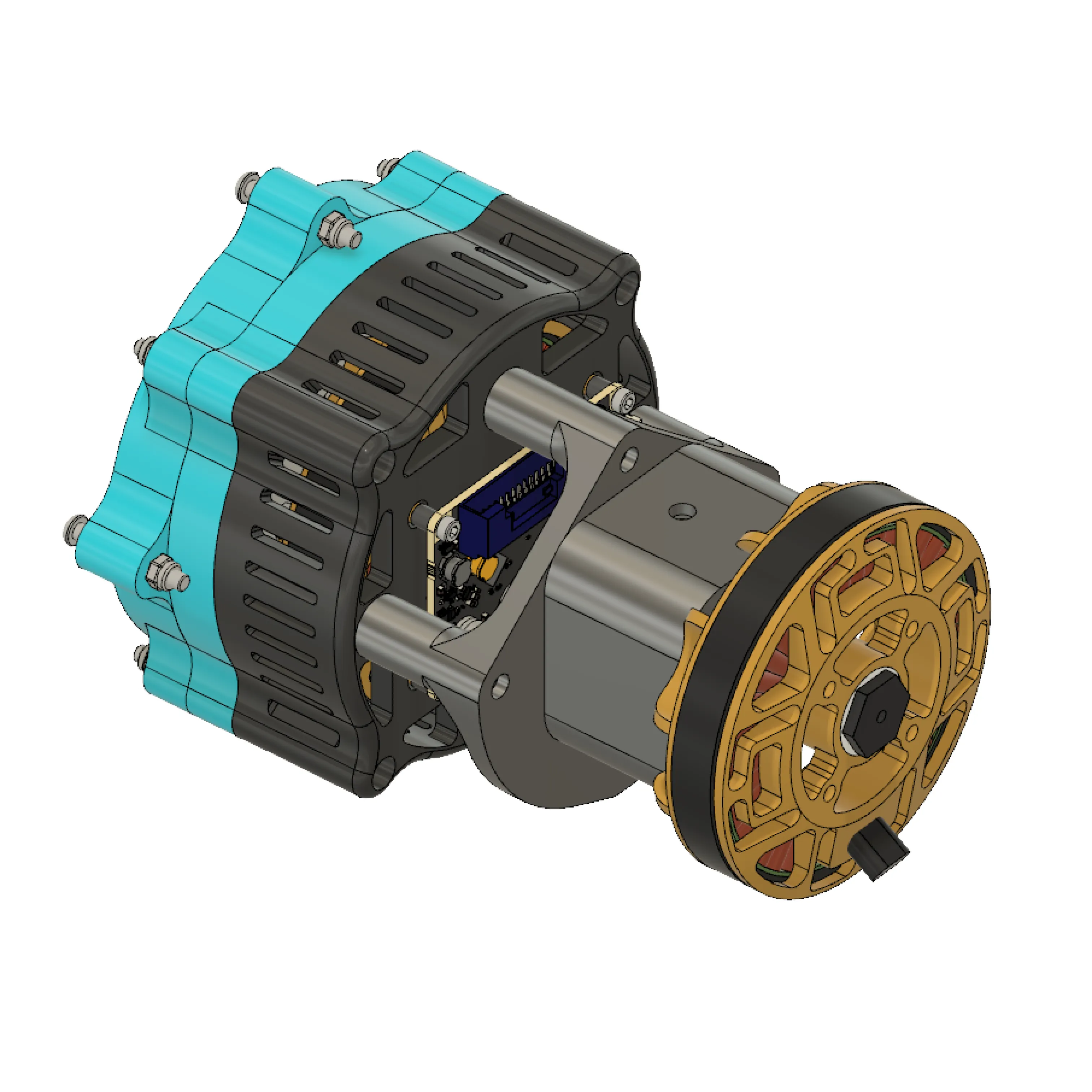
Electronics validation
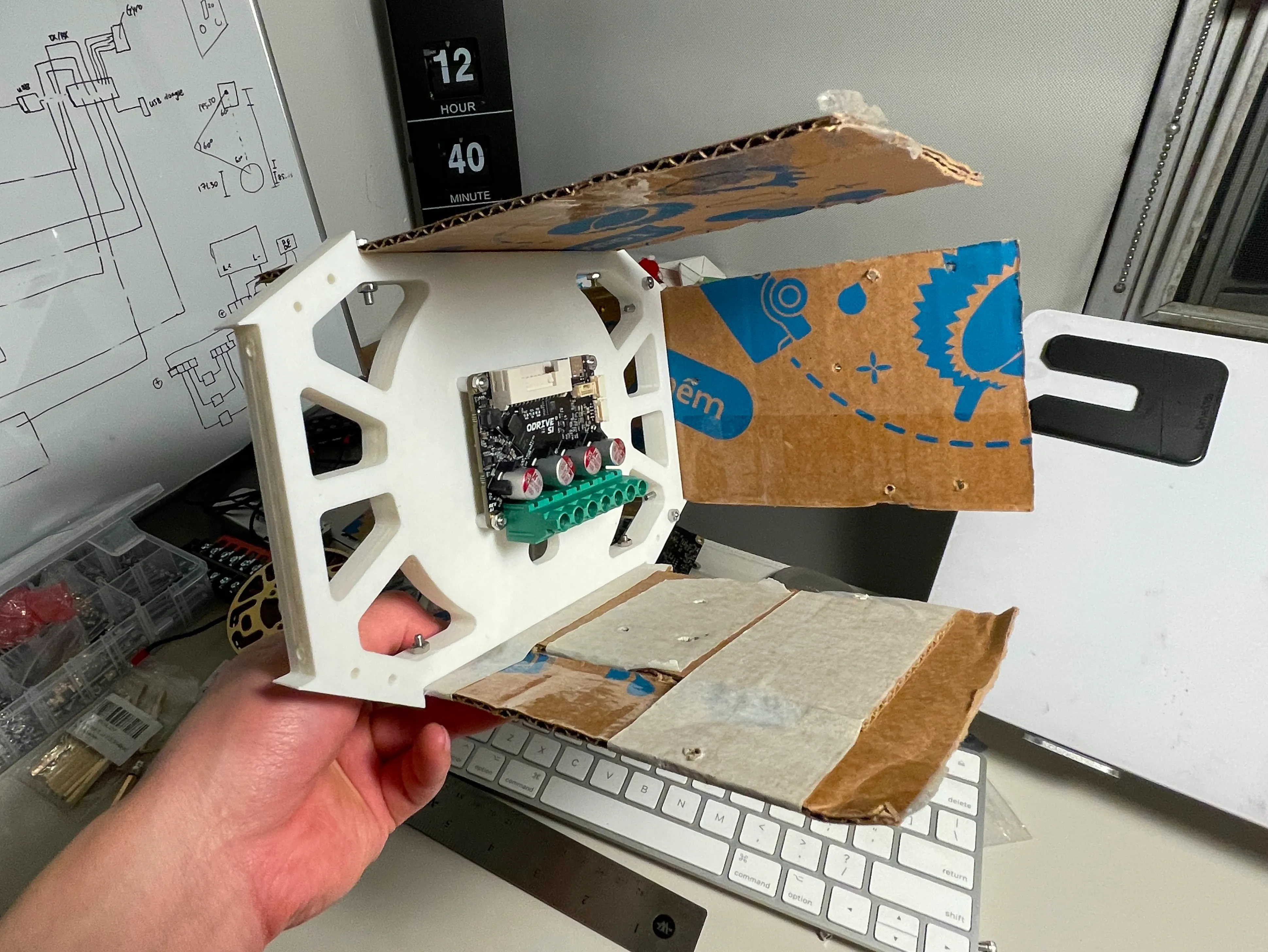
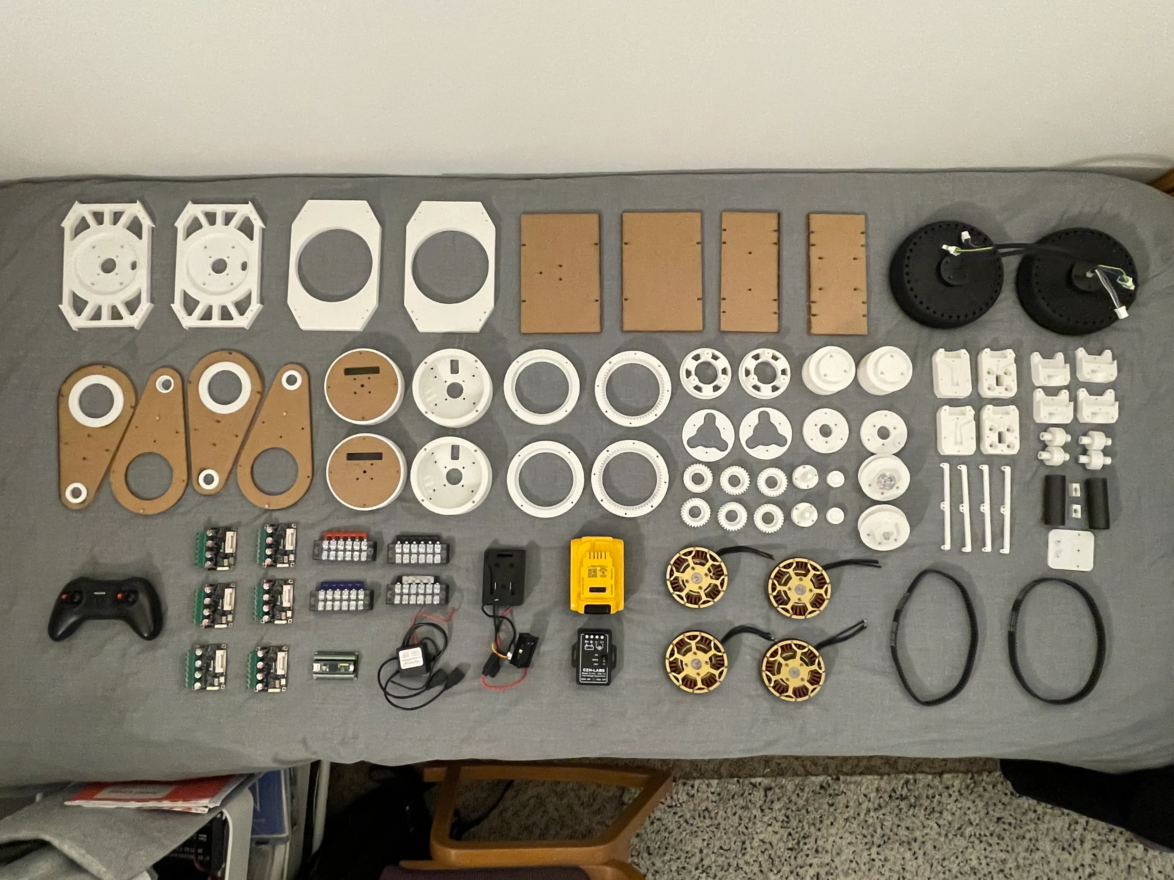
Prototyping and assembly
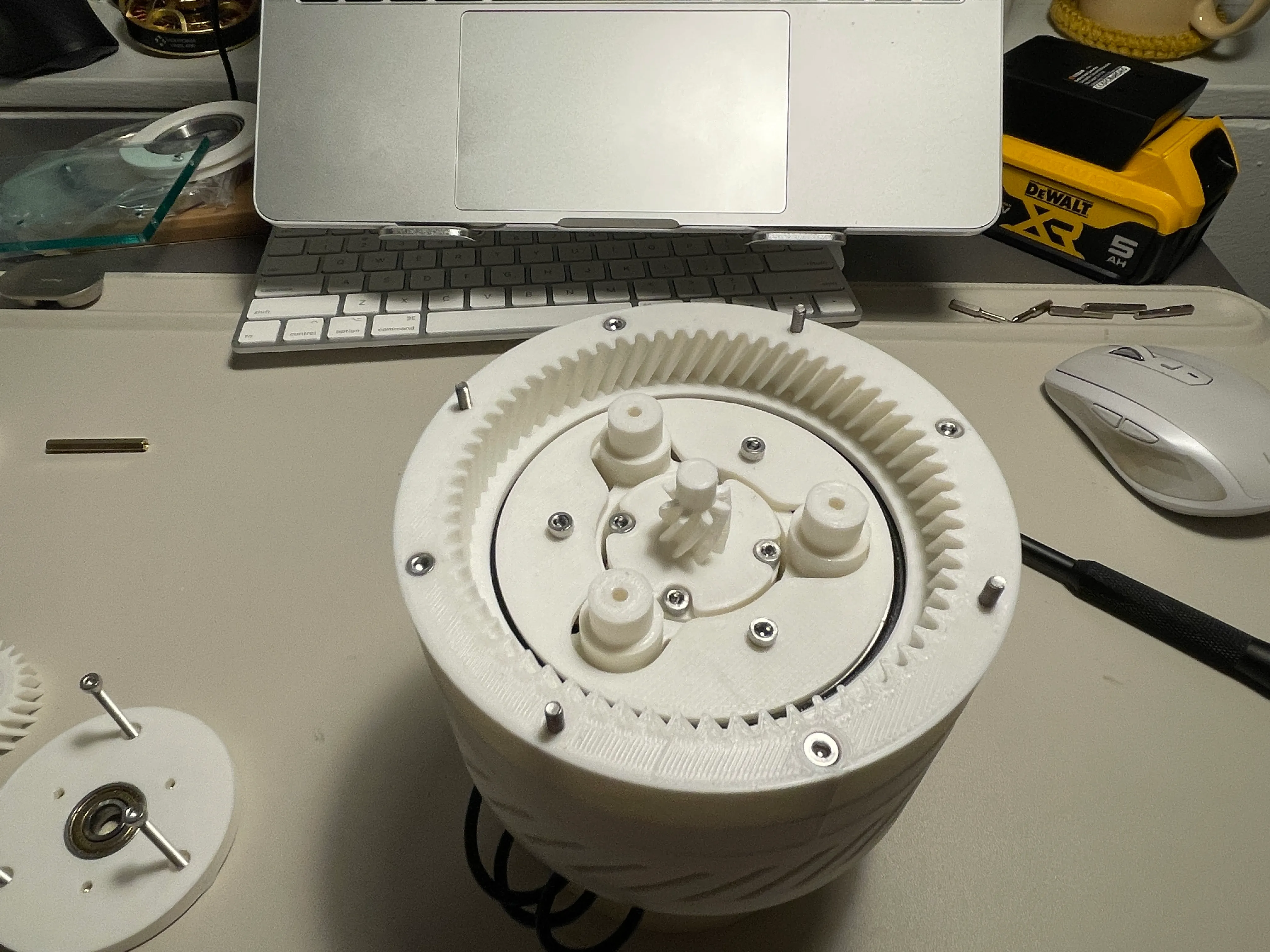
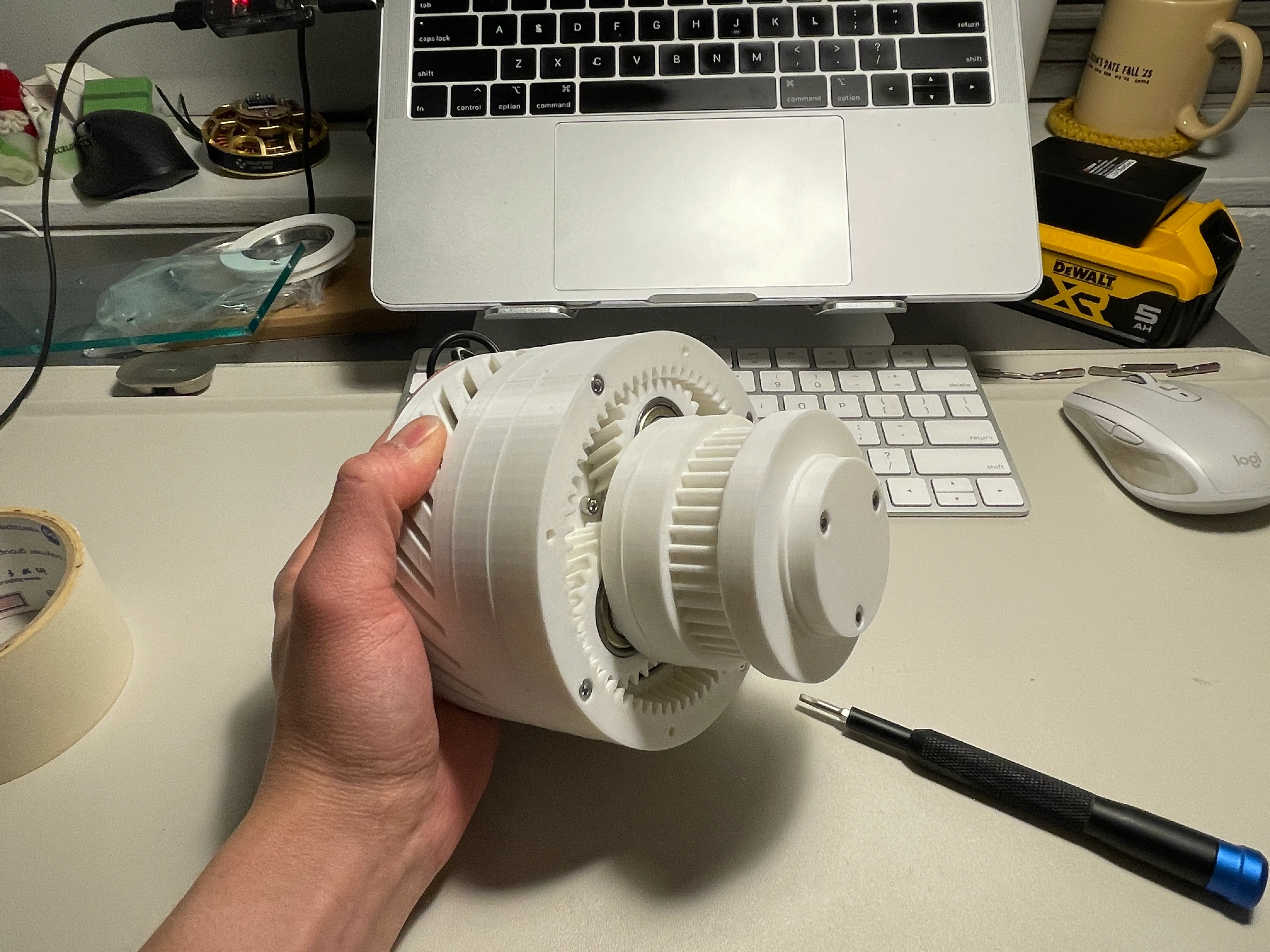
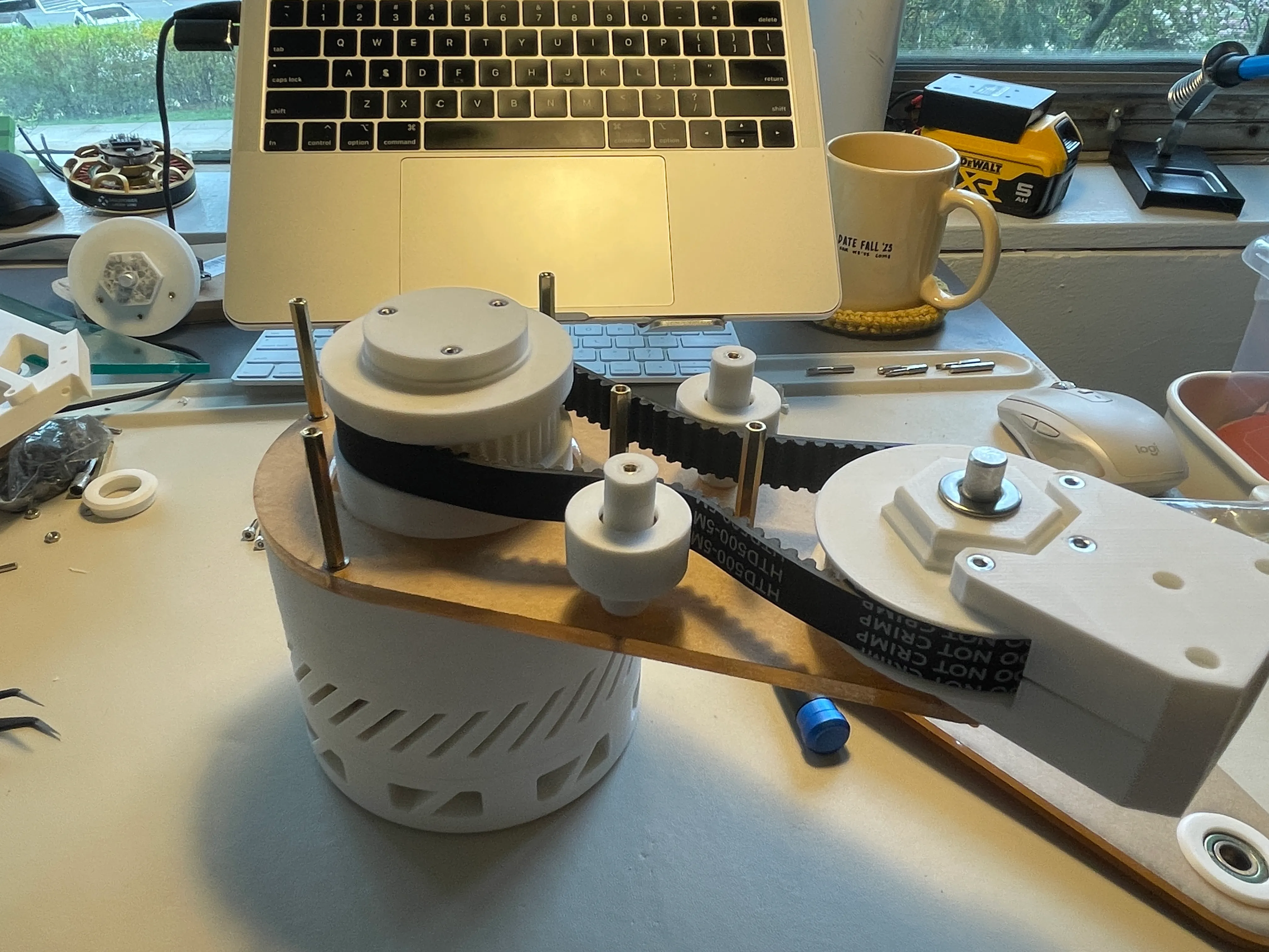
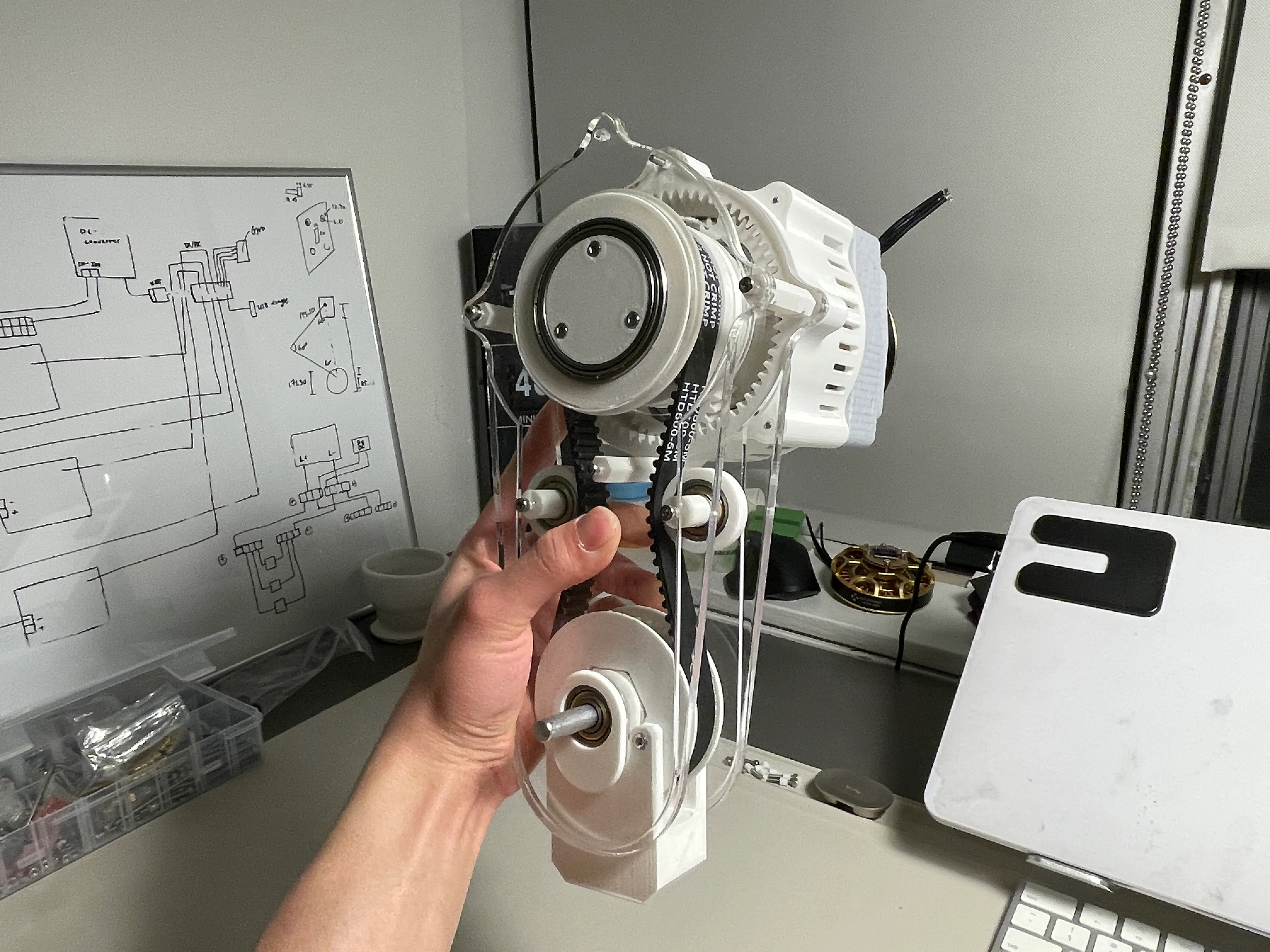
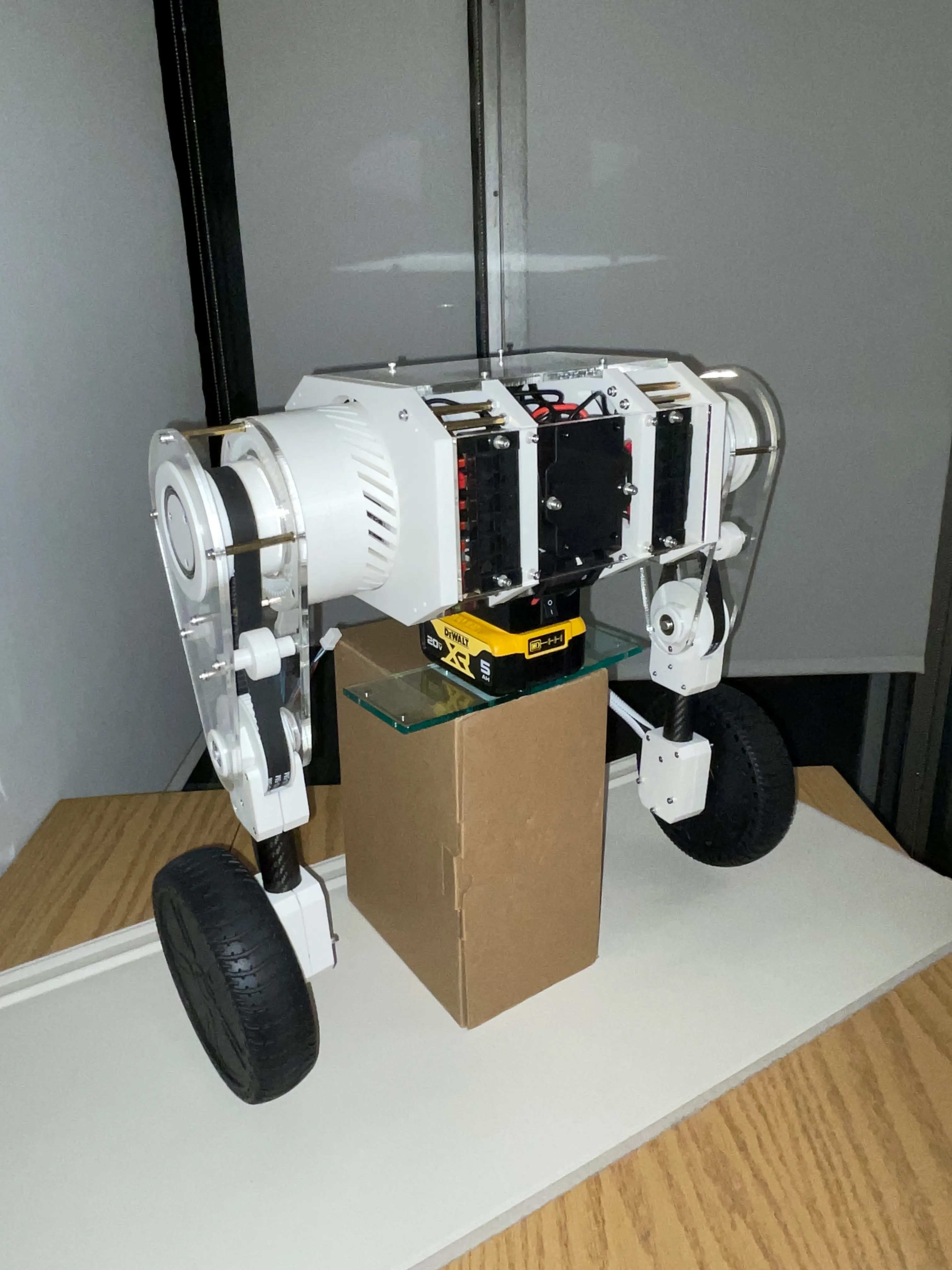
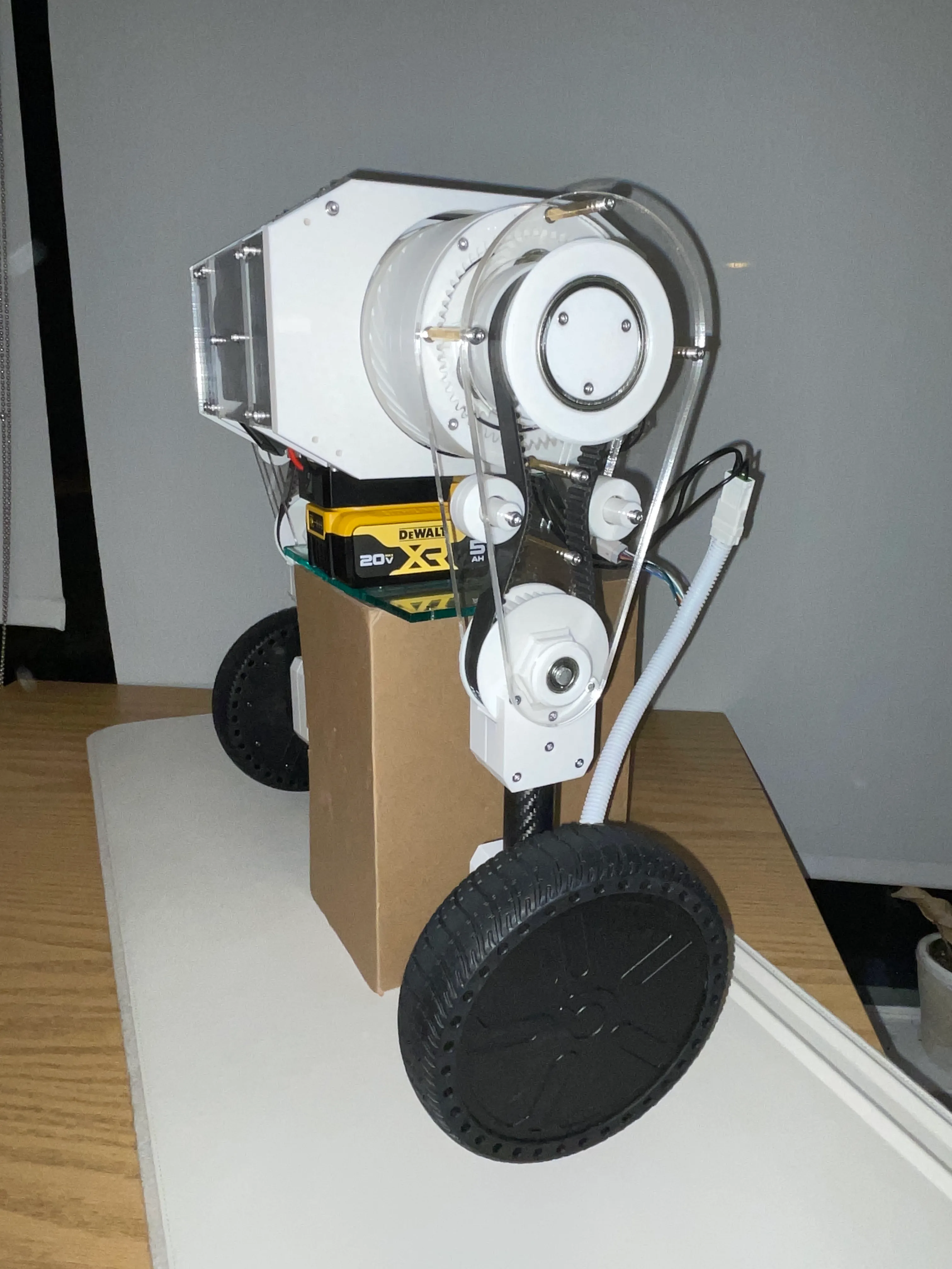
Final Design
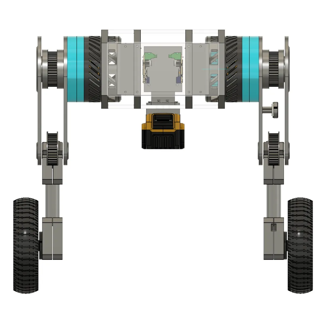
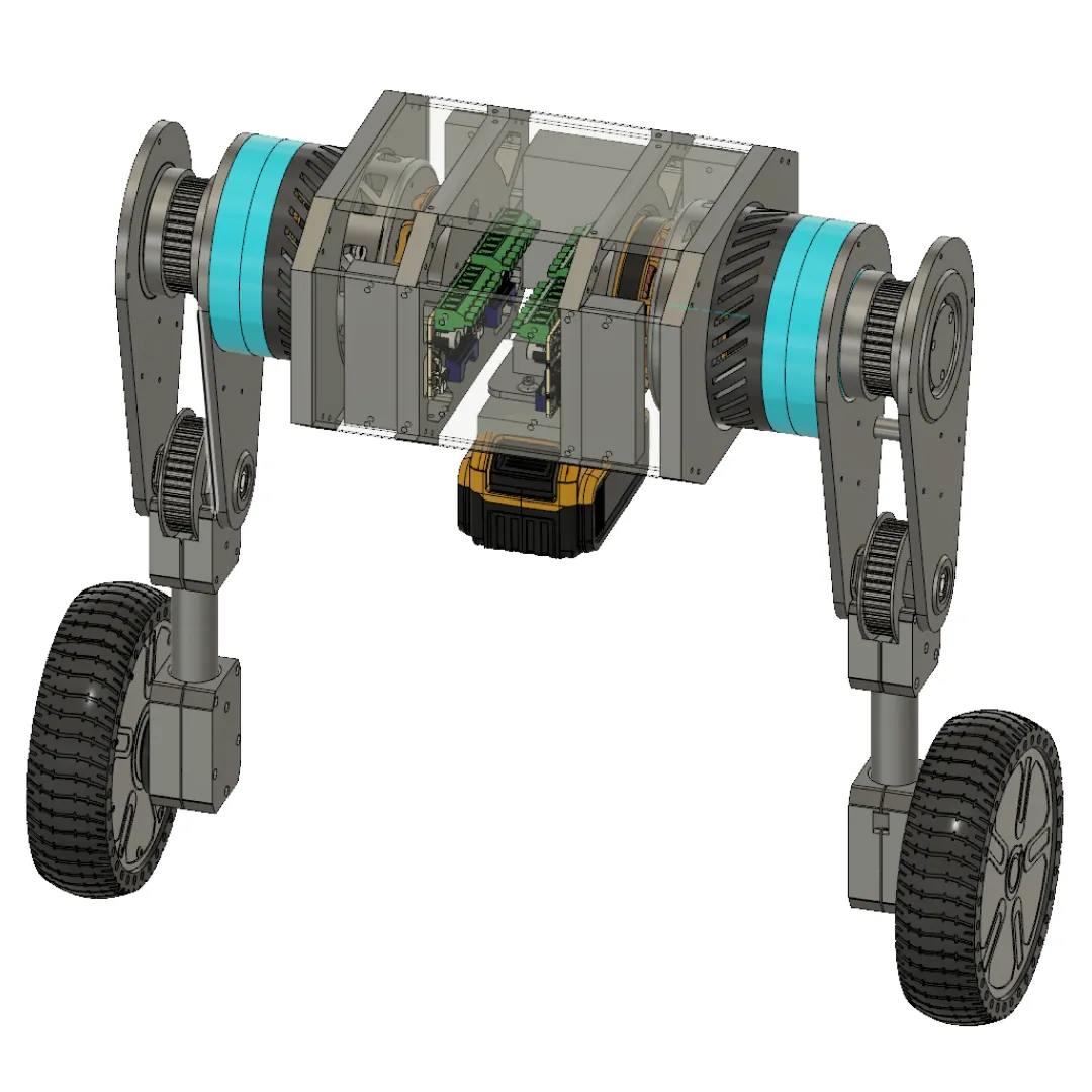
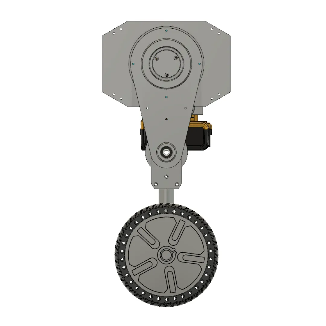
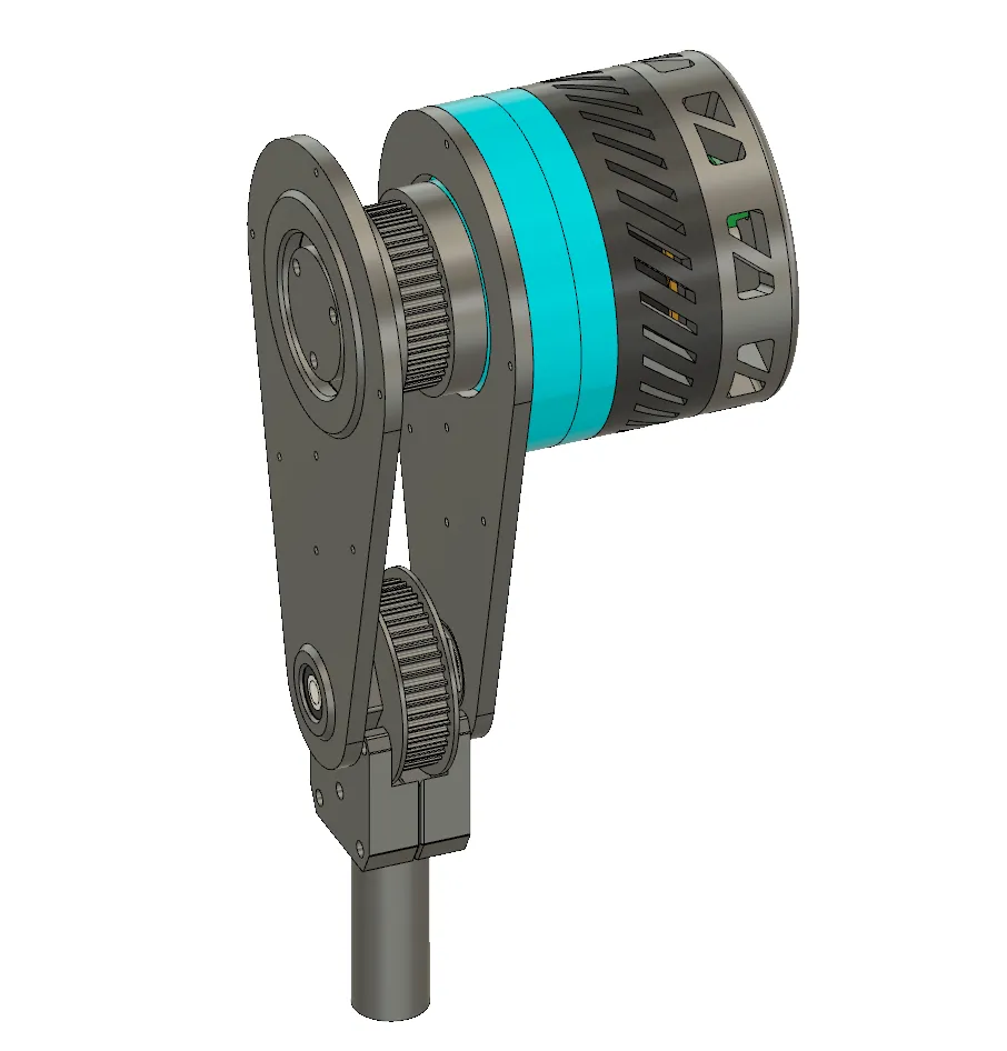
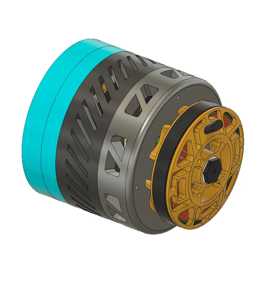
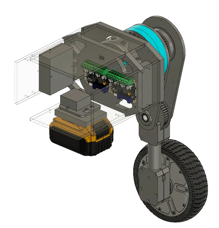
Challenges and Solutions
Foot Mount Splitting
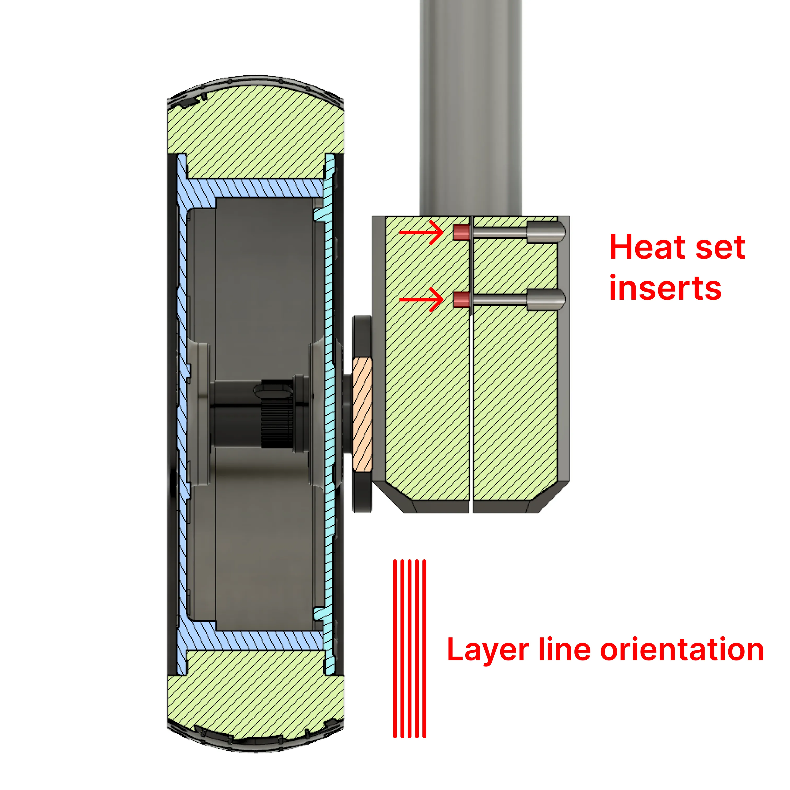
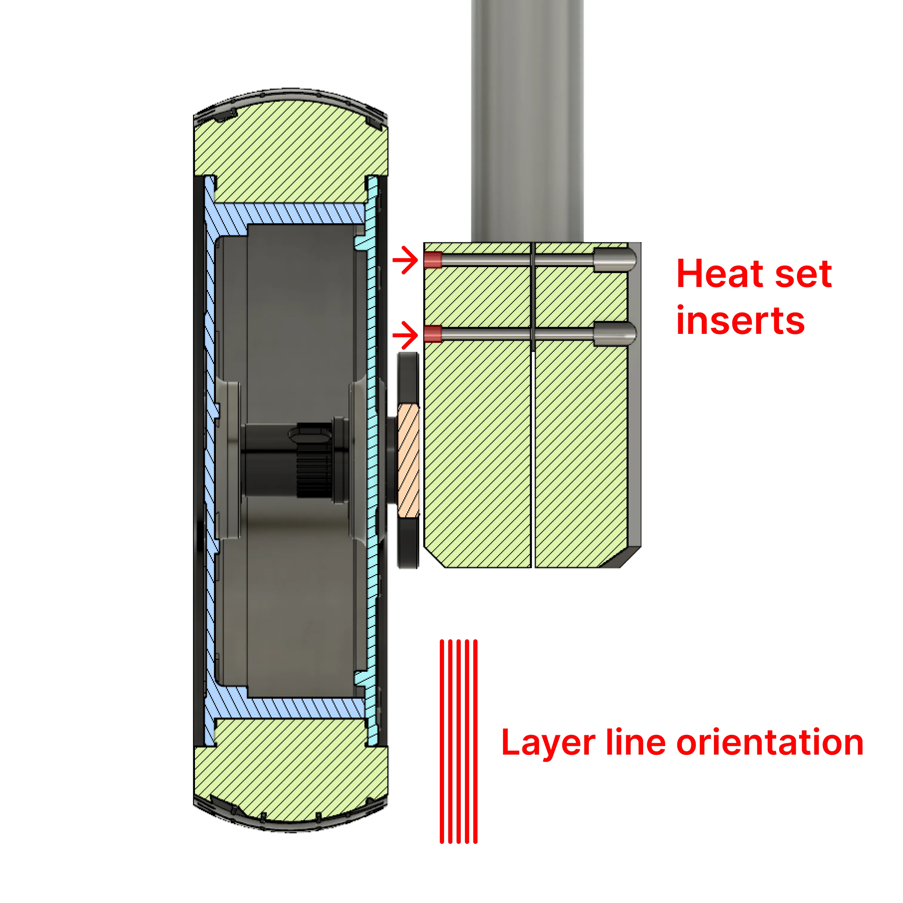
Challenge
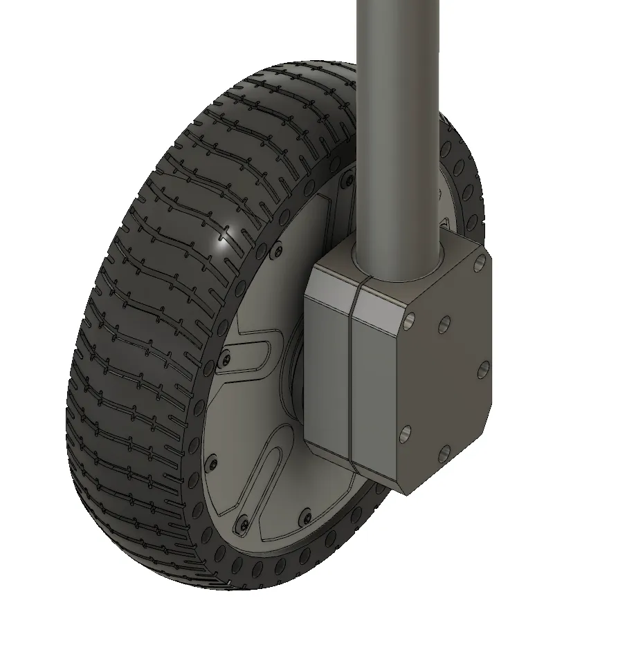
- The foot mount was splitting along layer lines due to the tensile load exerted on the plastic from the M3 screws
Solution
- Move the position of the heat set inserts to the outer side of the mount
- By moving the heat set inserts, the plastic experiences a compressive load from the M3 screw + insert, thus making the layer lines far less susceptible to splitting and cracking
Foot Mount Clamp
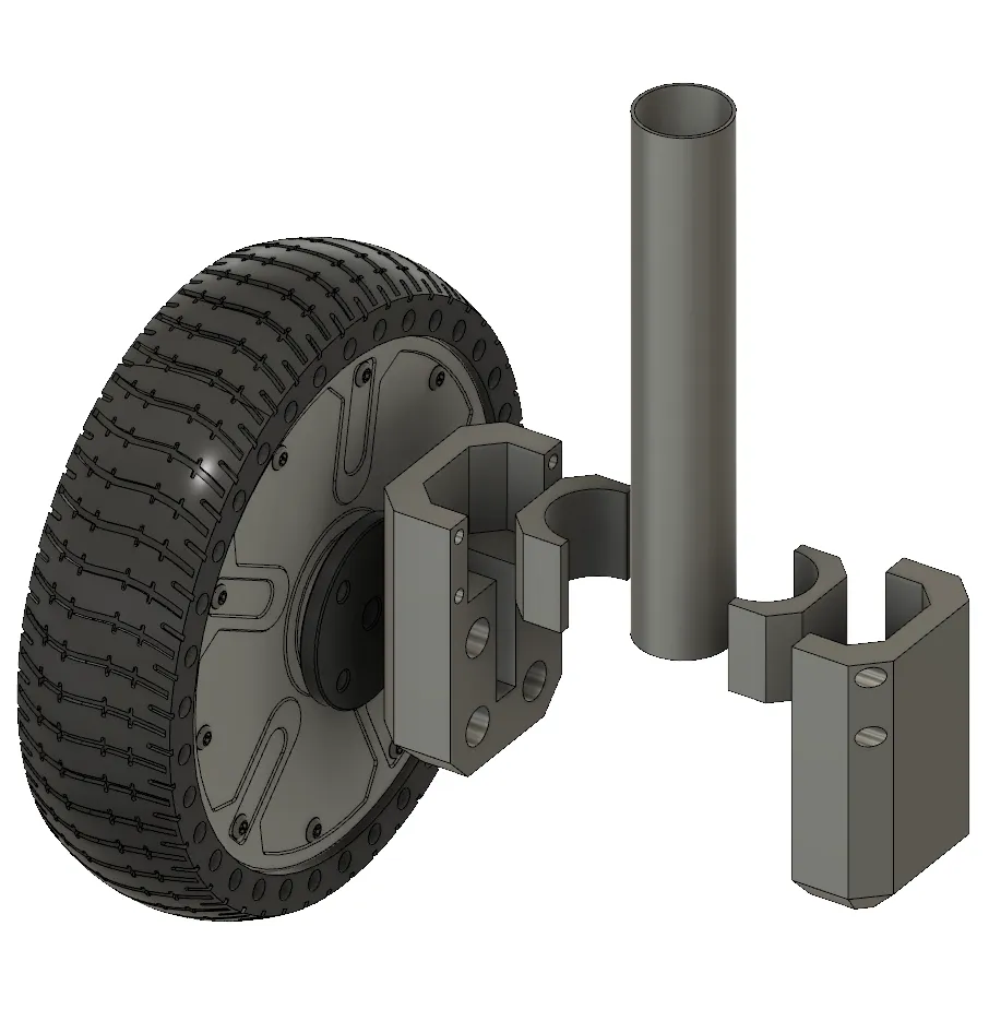
Challenge
- The carbon fiber tube was slipping out too easily from the foot mount
Solution
- In order to increase the frictional force acting on the tube, I knew that I either increase the friction coefficient of the materials or the normal force as dictated by the formula:
- In the second iteration, I made 2 design changes to the mount:
- Create an inner and outer mount that clamps around the tube through M3 bolts that provide a compressive force
- Add additional inner clamps that could be easily printed in a different filament material such as TPU in order to increase the friction coefficient between the piece and the tube
- Additionally, these pieces were smaller so they could be printed more easily in a finer resolution to achieve a better tolerance fit with the tube.
- In the final iteration, I removed the inner clamping pieces because they were unnecessarily large and the compressive force from the screws was enough to retain the tube in place
Laser Cutting Tolerance Issues
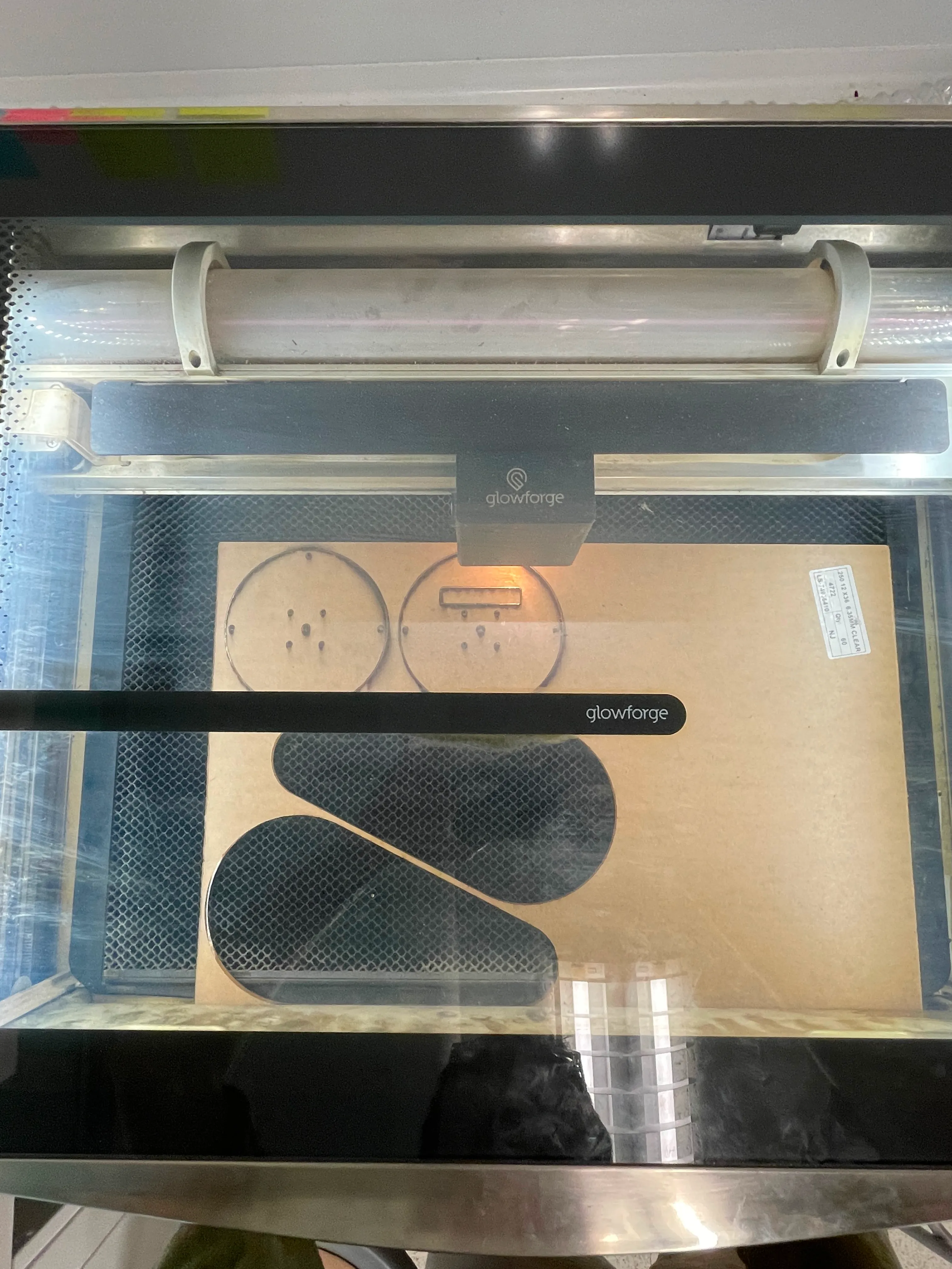
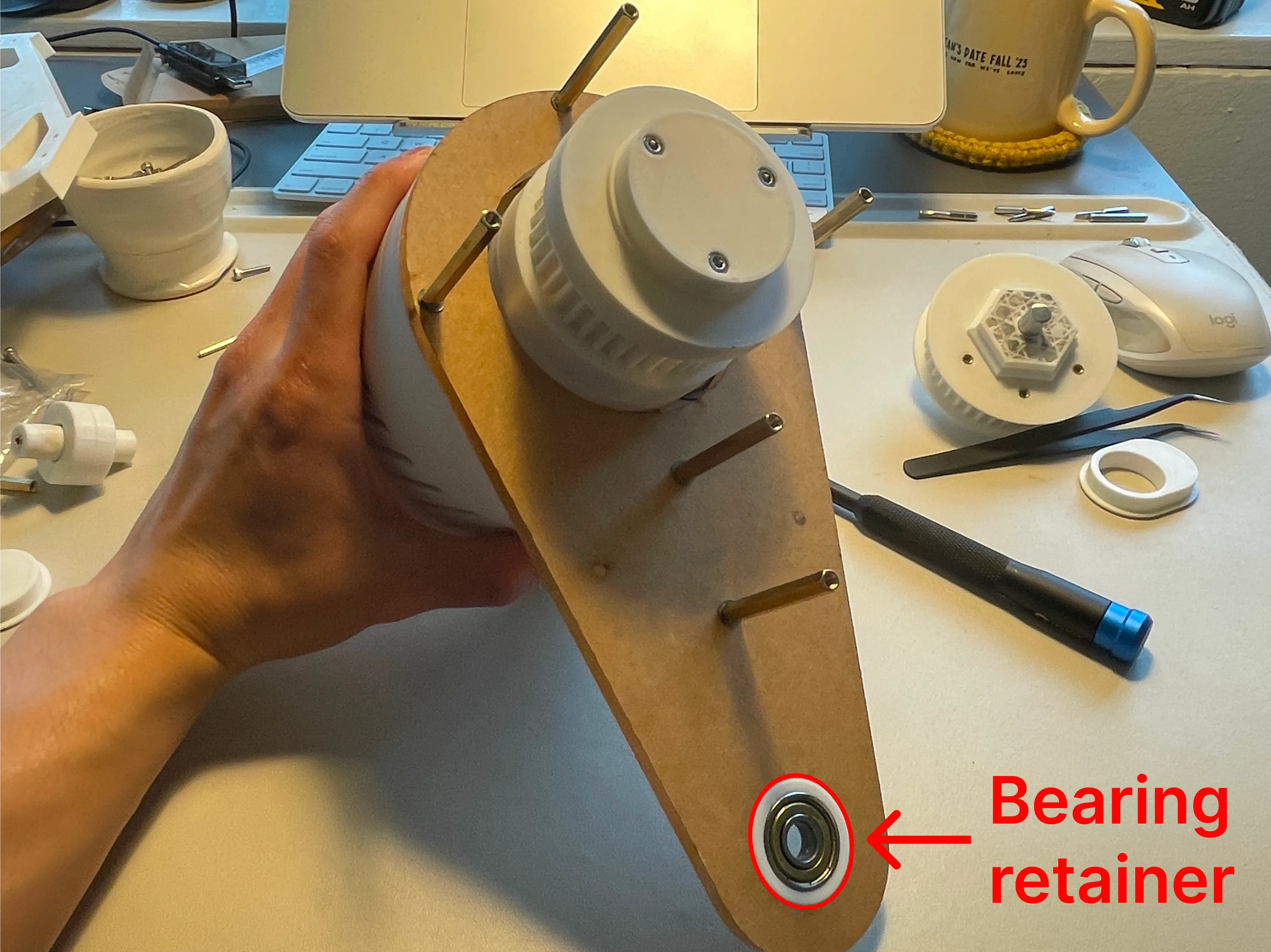
Challenge
- Tolerance issues from laser cutting kerf
Solution
- 3D print a retainer for the knee shaft bearing to fit inside the laser cut portion
- This piece was small enough to quickly iterate on the exact tolerance necessary to interface with the laser cut hole
Hip Joint Mount
Challenge
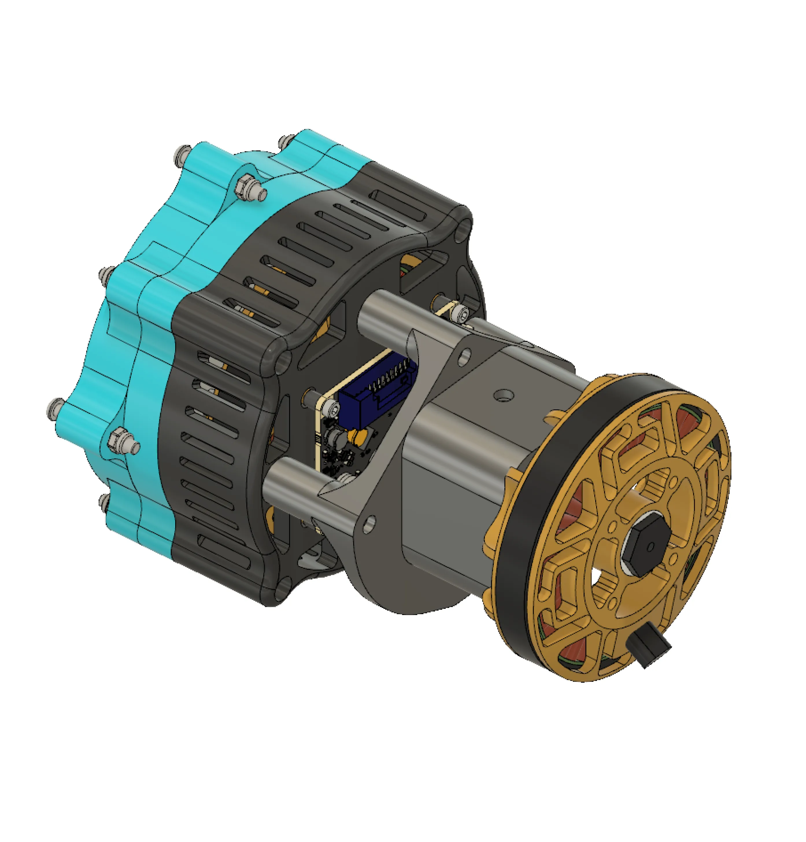
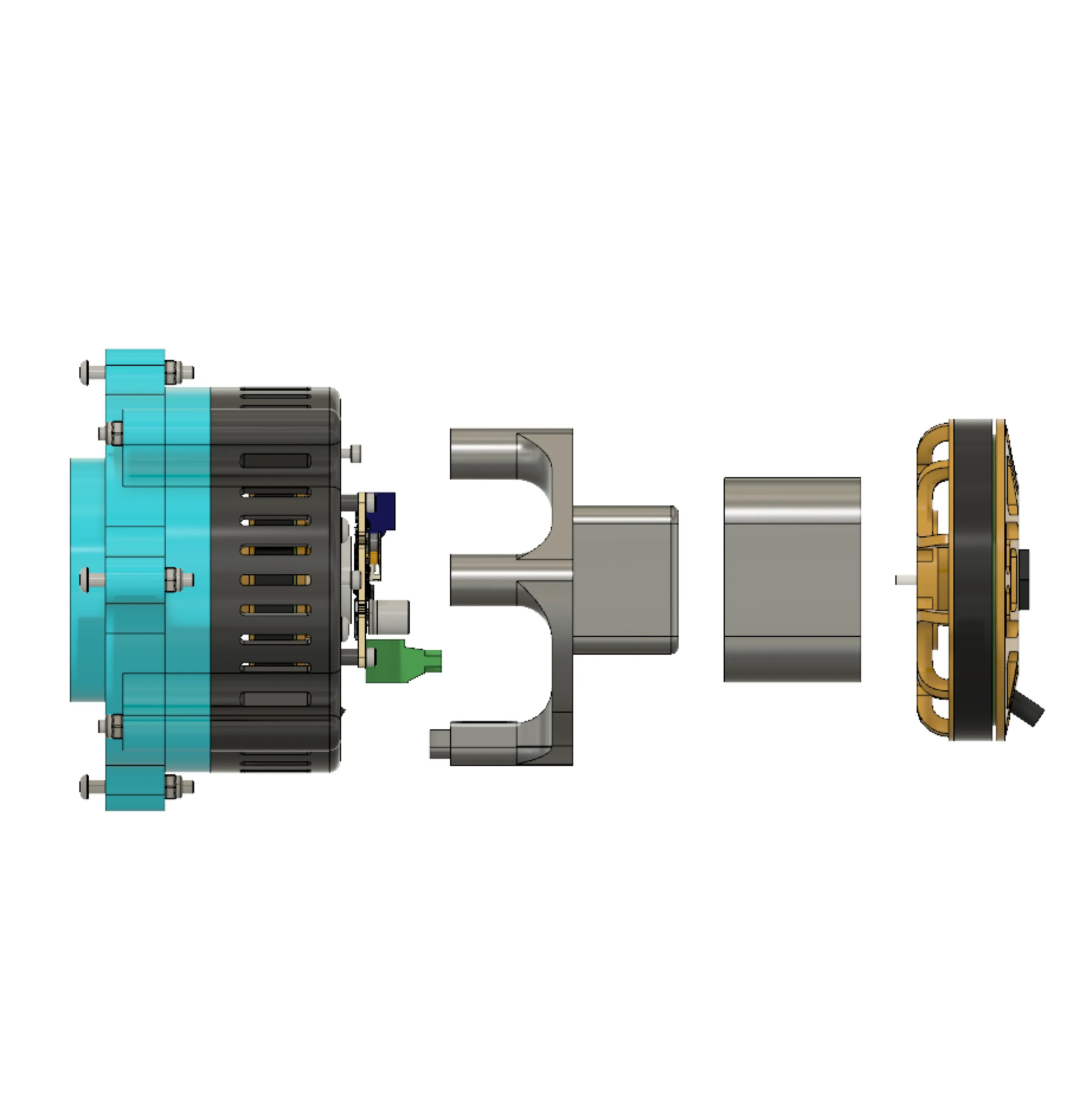
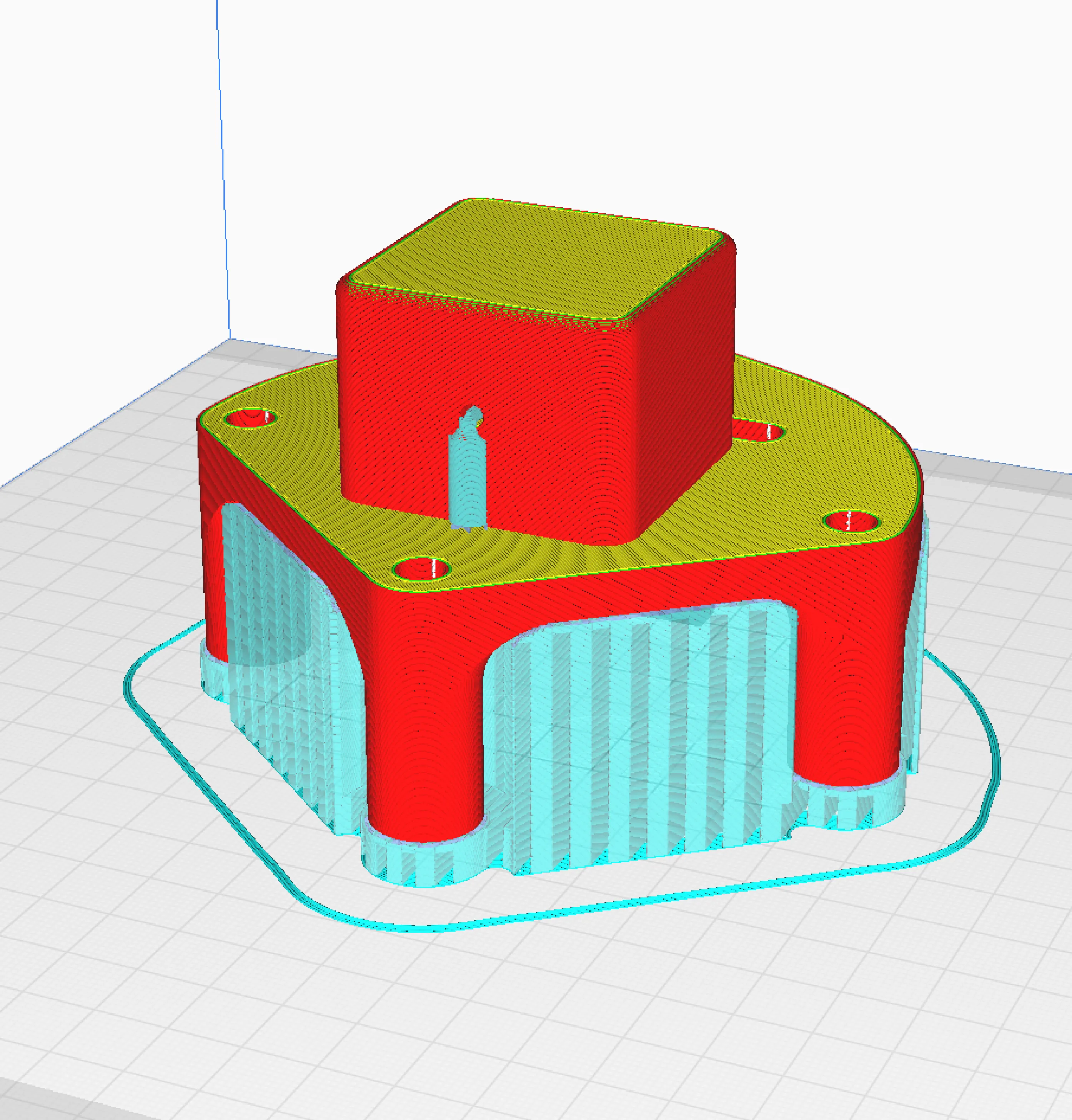
- In order to make the hip joint easy to assemble, the original design used a ‘mortise and tenon’ joint which ended up requiring extraneous support material and being overly bulky.
Solution
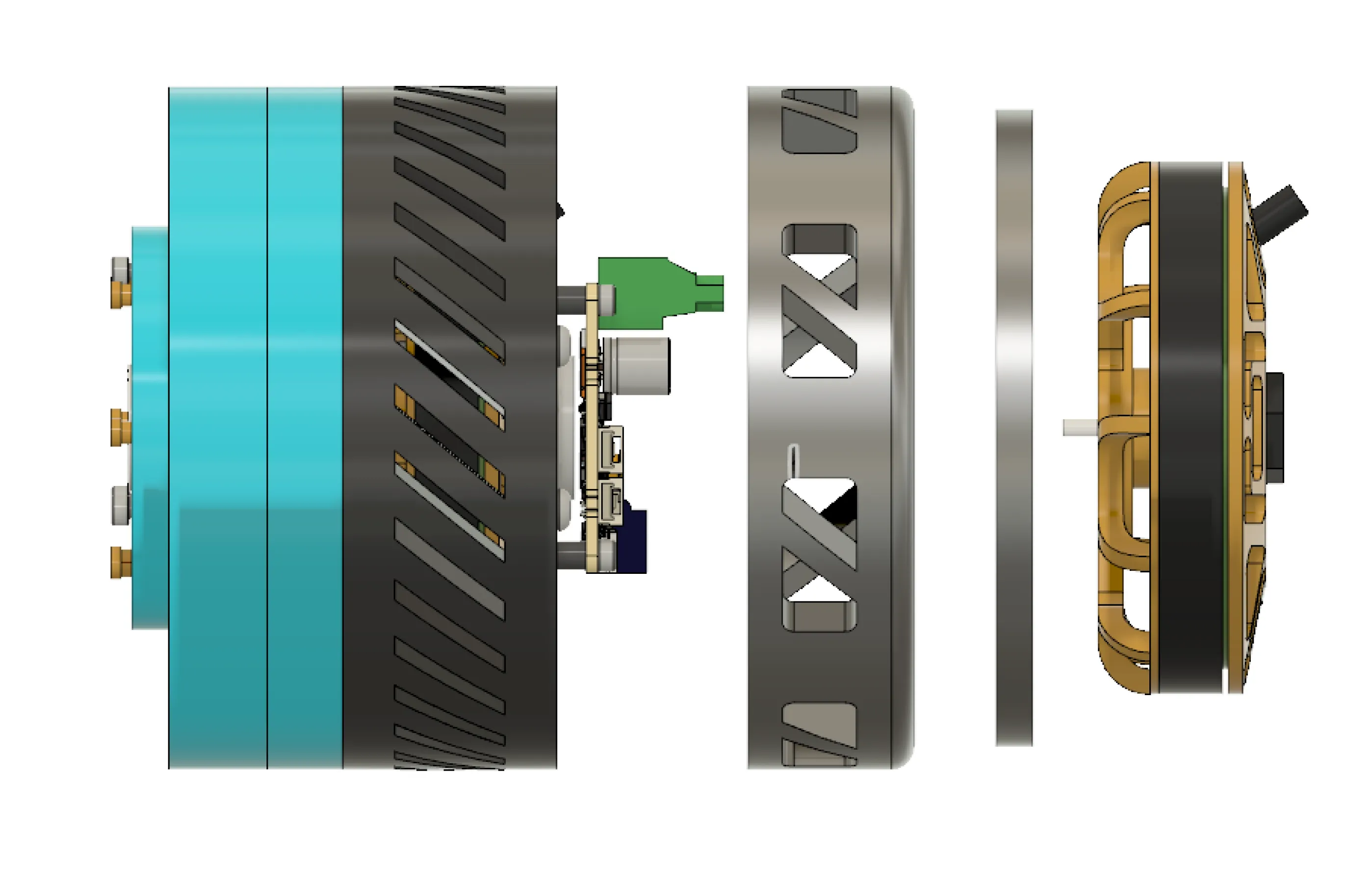
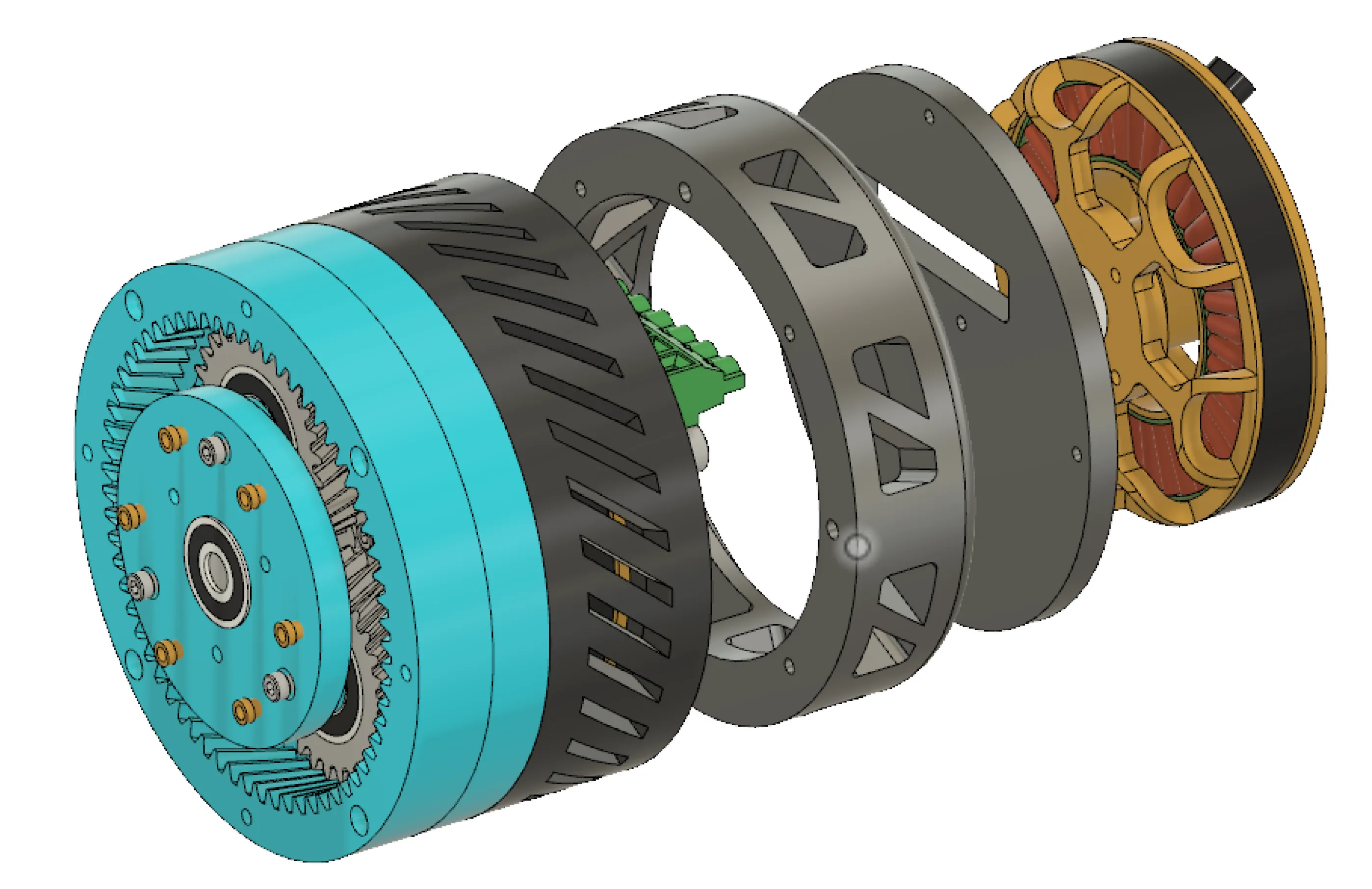
- Redesign the actuator housing to allow for easier integration of the hip joint
- This significantly reduced the size of the mount, allowing for a slimmer side-to-side profile
Results & Technical Details
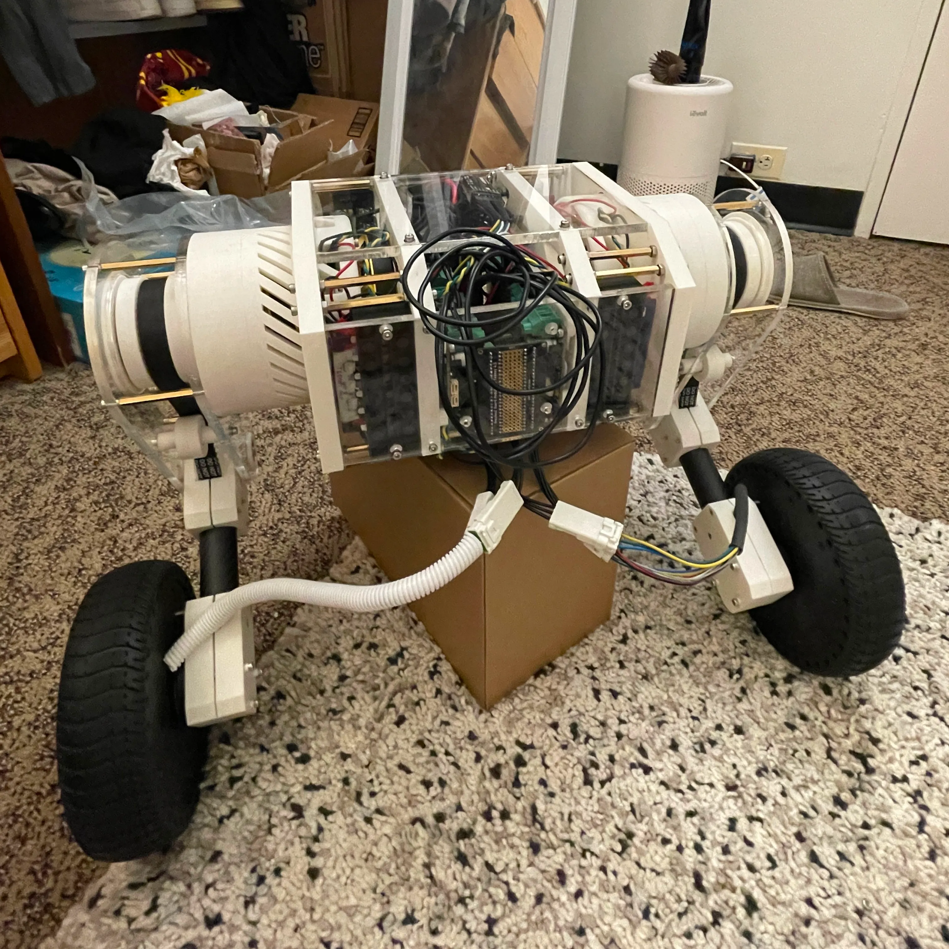
Max Rolling Speed: 1.56 m/s
Max Payload Capacity: 12.4 kg
Total Weight: 11 kg
Total Cost: $1750
The robot was successfully able to be remotely controlled to move each joint with the wheels. Unfortunately, due to time constraints, the balancing PID controller required additional tuning and was unable to independently balance on its own. Future plans are in place to finish the PID tuning to allow for robot balance.
Hardware Details
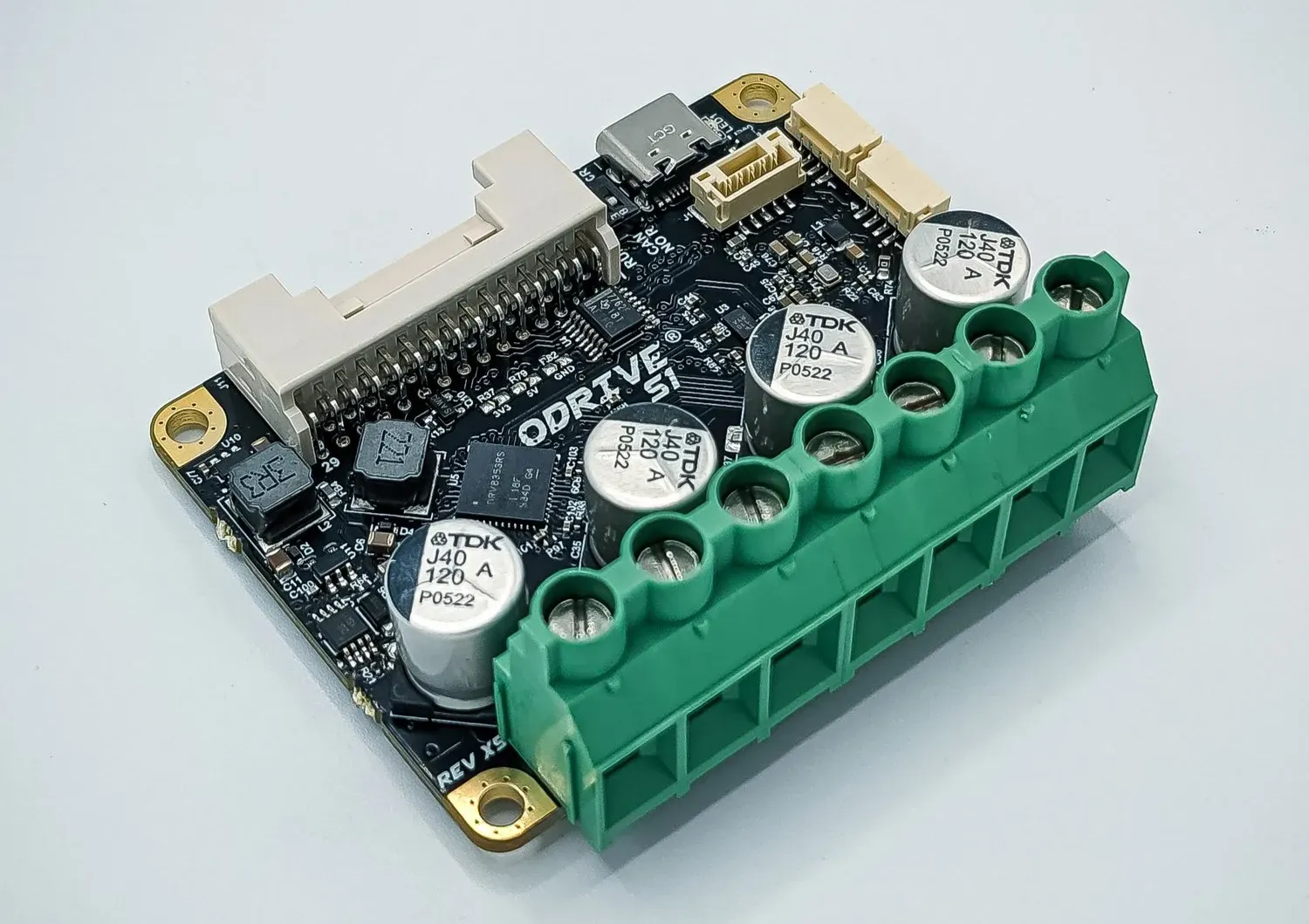
- ODrive S1 Motor Controller
- 20V power input
- Onboard absolute magnetic encoder
- Position, velocity, or torque control
- Communicated through serial communication
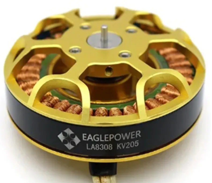
- Eaglepower 8308 Brushless DC Motor
- Total Mass: 336 g
- Diameter: 92 mm
- KV Rating: 90
- Idle Current (24 V): 0.6 A
- Max Continuous Current: 22 A
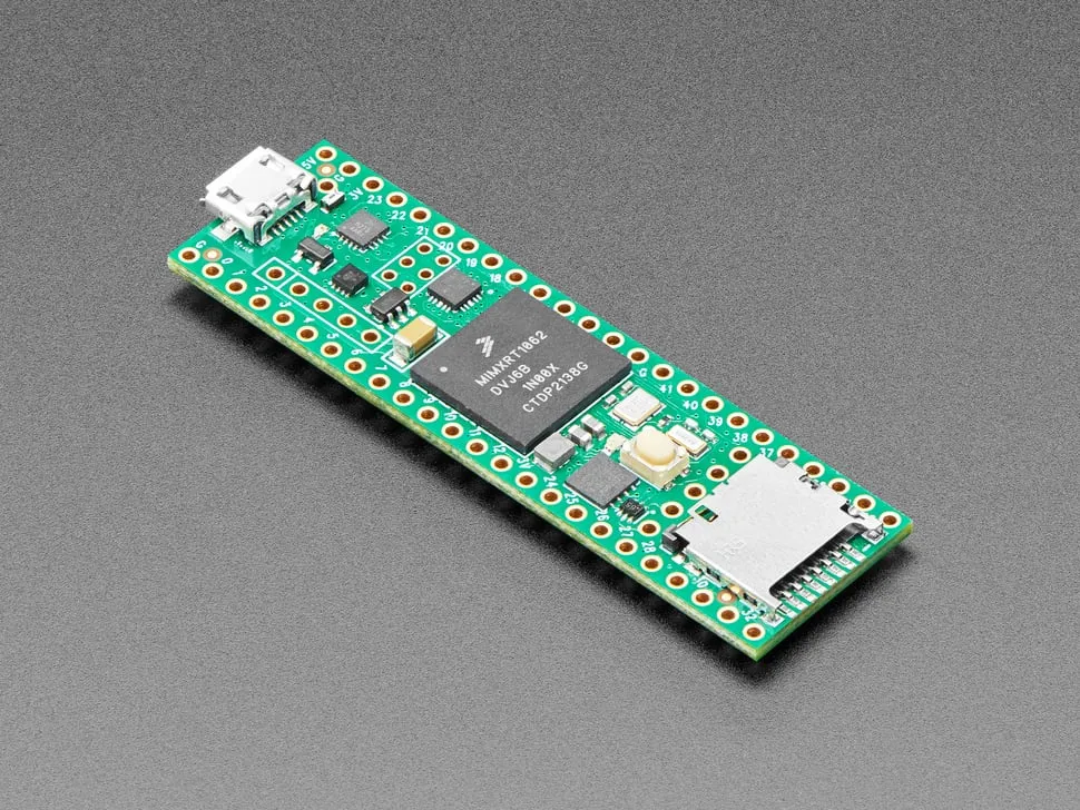
- Teensy 4.1 Microcontroller
- ARM Cortex-M7 at 600 MHz
- 7936K Flash, 1024K RAM
- 55 digital input/output pins, 35 PWM output pins
- 18 analog input pins, 8 serial, 3 SPI, 3 I2C ports
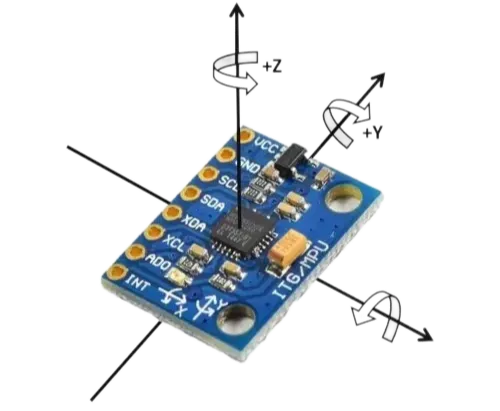
- MPU6050 Inertial Measurement Unit
- Integrated 3 axis gyroscope and 3 axis accelerometer
- I2C communication
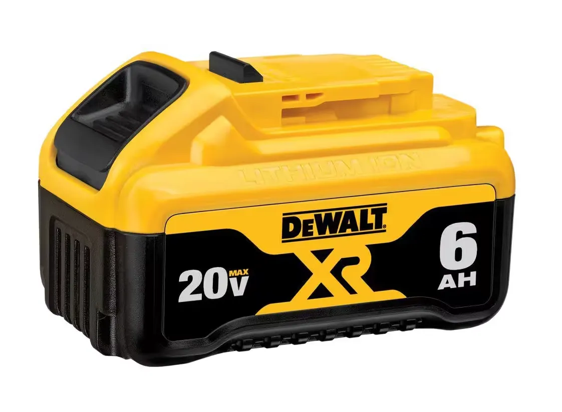
- DeWalt Tool Battery
- 20V output, 6AH
- Built-in battery management system
- Simple charging interface